Last Updated on March 16, 2024
It is important to give dual power supply, When we work with Operational amplifier or analog to digital conversion circuit. This article will help you to built dual power supply (+5V GND -5V) by using low cost voltage regulators. Use Center tap transformer in this circuit.
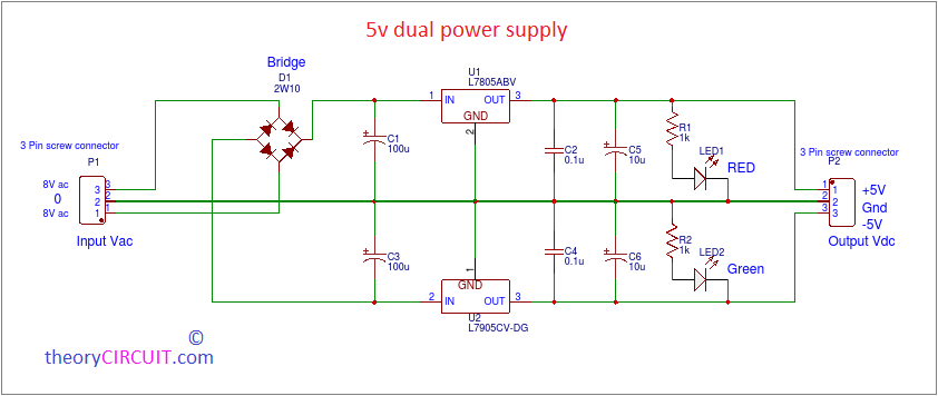
circuit diagram
Construction and Working
8-0-8Vac supply is obtained from centertap transformer (not shown in circuit) and the AC supply is directly applied to the Bridge rectifier Module or you can use four diodes in bridge format. Output from the Bridge will be rippled DC and it is filtered by using 100uF capacitors. Here center tap terminal taken as GND terminal. +V out from bridge rectifier regulated by IC7805 positve regulator and -v out from bridge rectifier regulated by IC7905 negative regulator.
Final stage filtering is performed by 0.1uF & 10uF capacitors. For Indication purpose we used RED LED at +ve output terminal and GREEN LED at -ve output terminal.
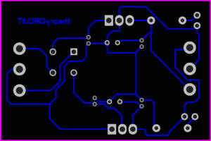
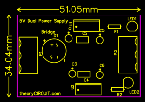
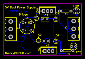
PCB
Here is the example Printed Circuit Board (PCB) design given, alter and draw using PCB design software depends on your expectations.
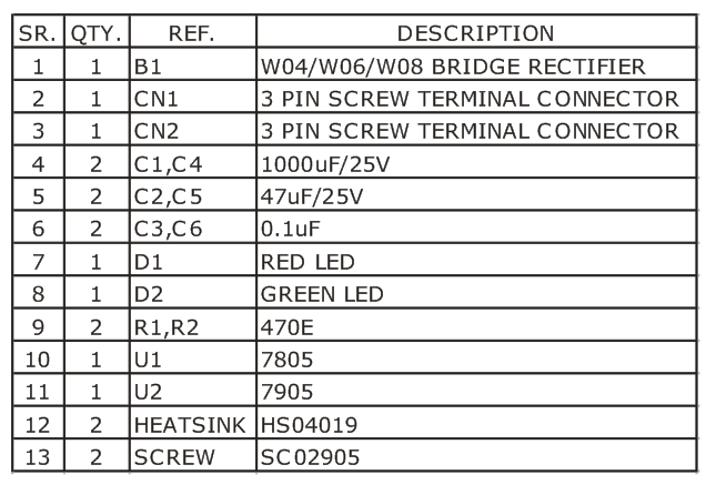
BOM