Last Updated on March 16, 2024
Many Controllers or output actuators requires both positive + and negative – supply with Ground (GND). By using battery power source or USB power source we can not provide those bias to circuit elements. Here we designed simple 5v Dual Power Supply Circuit which help us to convert single power source into dual power supply (+ and – with Gnd).
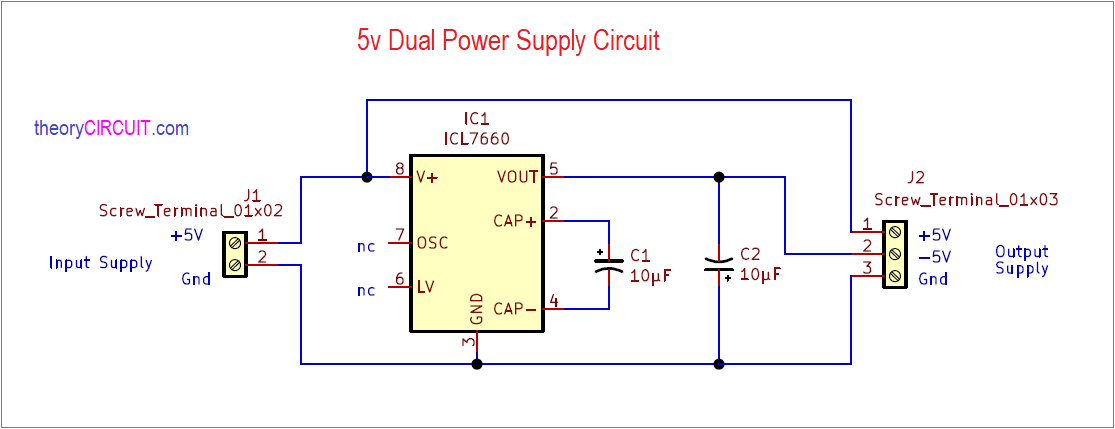
5v Dual Power Supply Circuit designed by using ICL7660, output of this circuit will be +5V and -5V dual power supply with Gnd. IC L7660 is a CMOS switched capacitor voltage converter Integrated circuit. It operates with only two external capacitors and capable of converting voltage from 1.5 V to 10 V.
Circuit Diagram
Components Required
- IC L7660 – 1
- Screw Terminal 01×02 – 1
- Screw Terminal 01×03 – 1
- Electrolytic Capacitors 10µF/16V – 2
- Use Gerber files for PCB
Construction & Working
IC L7660 contains a linear regulator, an RC oscillator, a voltage level translator, and four power MOS switches internally. To ensure latch-up-free operation, the circuitry automatically senses the most negative voltage in the device and ensures that the N-channel switch source-substrate junctions are not forward biased. The oscillator frequency runs at a nominal 10 kHz (for VCC = 5 V), but that frequency can be decreased by adding an external capacitor to the oscillator (OSC) terminal or increased by over driving OSC with an external clock. (details as appeared in ti datasheet)
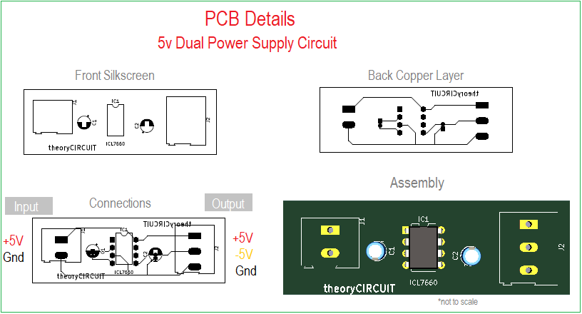
Printed Circuit Board – PCB files
5 V Dual Power Supply Circuit Gerber File
Interactive Board Viewer


After Soldering Necessary components in PCB connect 5 Volt power source at input and then you can receive +5 V, -5 V and common Gnd at output side.