Last Updated on March 24, 2024
Simple Adjustable Timer Circuit using 555 timer IC constructed to give alert sound for variable time limits, this circuit constructed as a monostable multivibrator and gives only one pulse for the time limit. This circuit has two timing elements VR1 and C1, here we can change the time duration of output pulse with the help of VR1 Resistor.
This Adjustable timer circuit using 555 has buzzer as an output element and starts to produce a buzzer beep sound when the output goes low. Check the Variable Resistor value and calculate the time period before putting this circuit into application. Monostable Multivibrator Calculator.
Quick Note of 555 Monostable Multivibrator
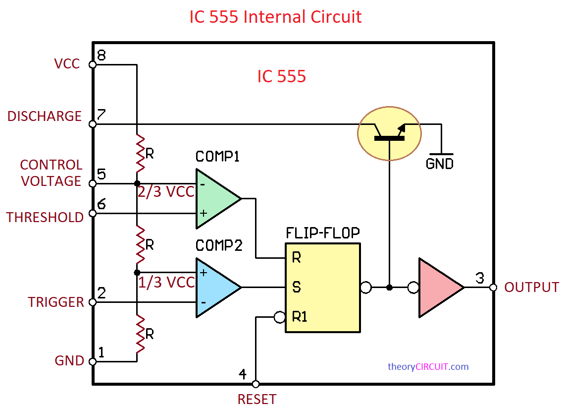
The 555 timer, a versatile integrated circuit, can be configured as a monostable multivibrator, a single shot pulse generator. In this mode, it generates an output pulse in response to the trigger input. When the trigger pulse is applied to the trigger (pin 2) that falls negative(1/3 VCC), the flip-flop of the 555 timer is set, causing the output (pin 3) to go high. The values of the external resistor and capacitor connected are determined as the timing components, the voltage at pin 6 increases until it reaches a threshold level (2/3 VCC), at which time the flip-flop is reset, and the output is low. Time which it takes and reaches this limit is determined by time constants (R – resistance and C – capacitance). Therefore, you can manipulate these external factors to control the stretching of Pulse duration. The monostable mode of the 555 timer finds use in various timing and pulse generation circuits.
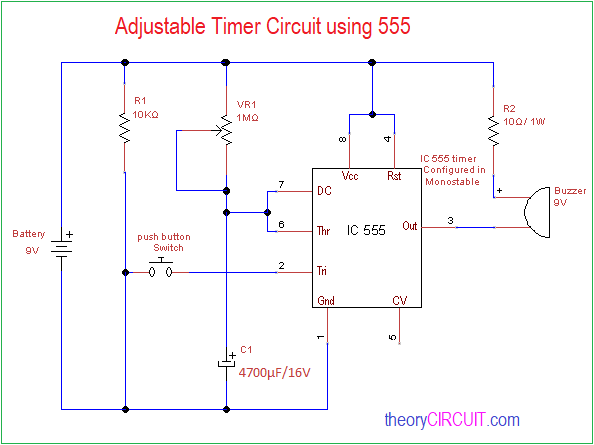
Circuit Diagram
Components Required
- IC 555
- 9V Buzzer
- Variable Resistor 1MΩ
- Resistors 10KΩ, 10Ω/1W each one
- Capacitor 4700μF/16V
- Push button switch
- 9V battery
Use IC 555 Timer Monostable Multivibrator Calculator for components and output Time (seconds) Selection.
Construction & Working
To construct the timer IC 555 circuit as a monostable multivibrator, the trigger pin should be connected to the ground supply through the push button switch. When the push button switch pressed the trigger pin gets negative supply and triggers the timer IC 555 operation. Timer components VR1 and C1 are connected across the power supply and discharge pin 7, threshold pin 6 are combined and connected to the timer elements. The output is connected to the 9V buzzer element through a 10Ω Resistor. Pin 8, 4 connected with 9V battery positive, pin 1 connected with 9V battery negative supply.
By varying the VR1 value we can adjust the output time limit, Calculate the output time limit before implementing the circuit on the field.
T = 1.1*R*C
T – Time period
R – VR1 value
C – C1 value
Test the time limit and VR1 value and make a label or mark on the circuit to select multiple time duration alert.
I had to search for the scale of the formula, one would need some significant values to get to minutes of delay. Hence the 1 Meg Ohm VR1, this circuit limit is about 16-1/2 minutes. So a larger resistor or larger C1 capacitor would be needed for a 30 or 60 minute delay.
T = 1.1RC
T – Time period — value in Seconds
R – VR1 value — value in Ohms (so 1K = 1000, 1M = 1000000)
C – C1 value — value in Farads (so 10uF = 0.00001, 1000uF = 0.001)
I am also thinking R1 should be connected to the other side of “push button switch” to pull pin 2 high when the switch is open.