Last Updated on March 16, 2024
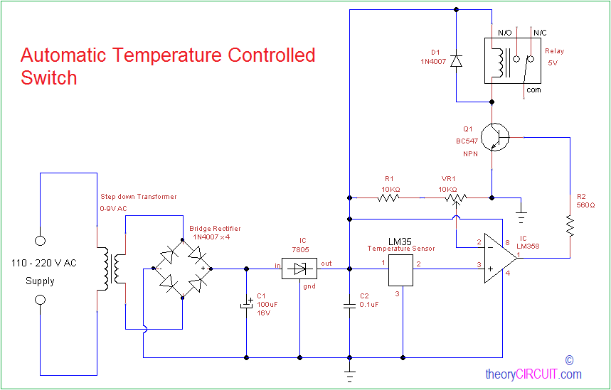
In some case we need temperature dependent output or temperature controlled output, the following circuit makes it automatically. Temperature sensor LM35 is used in this circuit to detect temperature and relay switch turns ON and OFF the target electrical load or appliances.
Once we tune the sensitivity (temperature) level this circuit becomes automatic temperature controlled switch, this circuit requires few affordable components and can be prototype with the dot board.
Circuit diagram
Construction & Working
First stage of this circuit is Rectifier and Regulator unit, high voltage AC (110 – 220V) supply is reduced to 9V AC with the help of step down transformer and then rectified into DC through bridge rectifier, C1 reacts as filter to eliminate AC ripples then linear regulator IC 7805 regulates DC voltage and gives constant 5V DC supply.
Temperature sensor LM35 gives output voltage linearly proportional to the centigrade temperature and LM358 operational amplifier help us to choose the temperature level through VR1 variable resistor, output of this operational amplifier is drives the Q1 transistor. Relay coil is connected between +5V and Q1 transistor collector terminal, when the output is higher than 2.5V from operational amplifier Q1 transistor turns ON and connect the relay coil to Ground supply hence the coil gets energized and makes the N/O (normally open) contact to closed one. By the way we can control electrical load or appliances automatically depends on temperature.
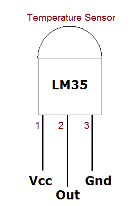
LM35 pin diagram
Note:-
- Know How the Relay works?
- This circuit involved in operation of High voltage either AC, Handle with extreme care and protections.
I need ideas about this
automatic temperature controlled circuit
Thanks for your interest stay in touch.