Last Updated on April 7, 2024
Charger circuit failure alarm Designed to alert when there is open or disconnected Battery from charger Circuit and also for damaged battery. This circuit designed by using two PNP Transistors and a Buzzer. If you need visual indication then you can use LED also as mentioned in the circuit.
Here two Transistor BC557 acts as a switch to connect the Buzzer to bias, When there is open or disconnected battery from charging supply.
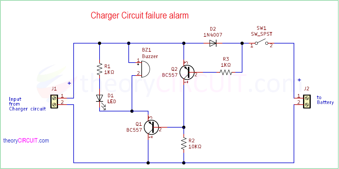
Charger Circuit Failure Alarm Schematic
Components Required (BOM)
| 1 | R1, R3 | 1KΩ | R_0805_2012Metric | 2 | ||
| 2 | R2 | 10KΩ | R_0805_2012Metric | 1 | ||
| 3 | D2 | 1N4007 | D_0805_2012Metric | 1 | ||
| 4 | SW1 | SW_SPST | SW_DIP_SPSTx01_Slide_9.78×4.72mm_W7.62mm_P2.54mm | 1 | ||
| 5 | BZ1 | Buzzer | Buzzer_12x9.5RM7.6 | 1 | ||
| 6 | LED1 | LED | LED_0805_2012Metric | 1 | ||
| 7 | Q1, Q2 | BC557 | TO-92_Inline | 2 | ||
| 8 | J1, J2 | Screw_Terminal_01x02 | TerminalBlock_bornier-2_P5.08mm | 2 |
You can use THT (Through Hole) Components for Breadboard or dot PCB board based circuit.

Construction & Working
Charger Circuit Failure Alarm designed to detect the improper current consumption, open circuit of load battery or any other disconnected device. This circuit is suitable for 3 Volt to 15 Volt with 1 Ampere maximum current environment, as always we need to give little high voltage to its input, for an example you are going to implement it on 3.7V battery then you need to give at least 4.7V input to this circuit. DC supply from charger circuit is picked up through J1 connector and then Buzzer, LED connected between DC supply through Q1 transistor. Base terminal of Q1 is connected between the Q2 transistor collector terminal and R2 Resistor. DC supply to the battery is connected to the J2 through D2 diode and SW1 switch. Here D2 diode used to prevent Reverse Polarity.
If there is a minimum charging current flow (5mA) to the load occurs then the Diode D1 and D2 conducts bias and Q2 transistor receives it through R3 Resistor, So the transistor Q2 stays in Saturation condition and there is no bias to Base terminal of Q1 transistor so that Q1 stays in OFF condition. When there is no Current flow, Transistor Q2 dont receive base supply through R3 and so it stays in Cut OFF condition. Now the Transistor Q1 gets bias through R2 and goes to Saturation region (ON), so the buzzer makes beep sound and LED glows. These indicates a problem in load.
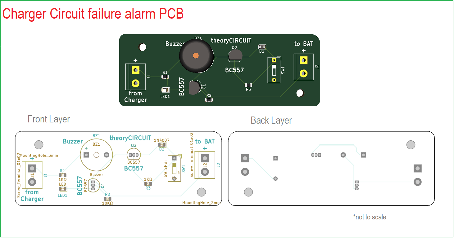
Printed Circuit Board (PCB)
Charger Circuit Failure Alarm Gerber Files.
Interactive Board Viewer


Working Video
I want to compliment you for this ‘Charger Failure alarm circuit’, I request you could mention to me the voltage range at the ‘Input from charger circuit’ point.
Thanks
Hi madhu
The Voltage range at the ‘Input from charger circuit’ can be from 4.5V to 12V. (Current should be less than 1 A)