Last Updated on March 16, 2024
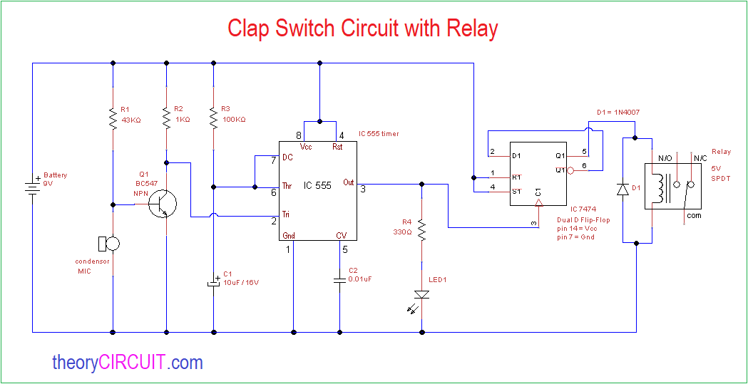
If you want to design a Switch circuit to turn ON and turn OFF without reach a physical switch then try this simple Clap Switch Circuit with Relay, this circuit is designed with timer IC 555, dual D flip flop IC 7474 and a electromagnetic Relay.
This circuit will turn ON or turn OFF the load connected with Relay when you clap or make louder sound trigger to this circuit, a simple condenser mic is act as a sensor in this circuit.
Circuit Diagram
Components Required
- IC 555 timer
- IC 7474 dual D flip flop
- 5V Relay (SPDT)
- Condenser Mic
- Transistor BC 547 NPN
- LED
- Diode 1N4007
- Resistor 43KΩ, 1KΩ, 100KΩ, 330Ω each one
- Capacitor 10μF, 0.01μF
- Battery 9V
Construction & Working
This circuit has three stage one is sound detector stage this is constructed by Condenser mic and transistor BC 547 as a level shifter, then second stage is timer IC 555 and this IC employed as a monostable multivibrator which will produce one timing pulse depends on timing Resistor R3 and timing Capacitor C1, when it receives trigger input from sound detector stage.
Output pulse from timer IC is directly fed into third stage that is D flip flop, here the Input pulse is makes the D flip flop into either SET or RESET position, the Relay is connected at the Q output of D flip flop, this Relay gets energized and turn ON load during set condition and turn OFF load during Reset condition.
Note:- This circuit constructed without any load connection at Relay. How to use Relay?
Condenser Mic
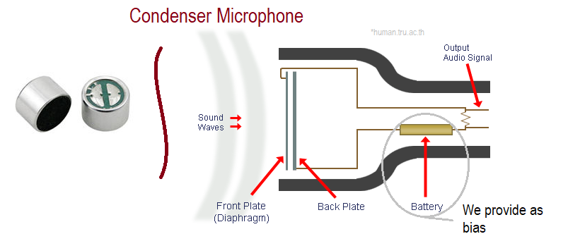
Condenser microphone available in different size and all are working in the same way, A condenser mic will have Fixed back plate and Movable front plate (Diaphragm), and separated by air (insulator), when the sound wave hits the front plate then it moves according to the sound wave and makes the different capacitance level and this signal can be used as electric audio signal, condenser mic requires bias and amplifier for to produce electric audio signal.