Last Updated on April 20, 2024
Many electronic circuits and microprocessor or microcontroller require a source of signal with specific frequency and amplitude, we can not provide many power supply source to individual components in the circuit, hence we use Oscillator circuits to provide different levels of signals to different circuit elements. Here simple colpitts oscillator circuit is designed to produce constant sinusoidal output.
As like other Oscillator circuit Colpitts oscillator also has the Tank circuit, Amplifier and feedback path. This circuit maintains positive feedback between amplifier and tank circuit and also provides undamped oscillation at output.
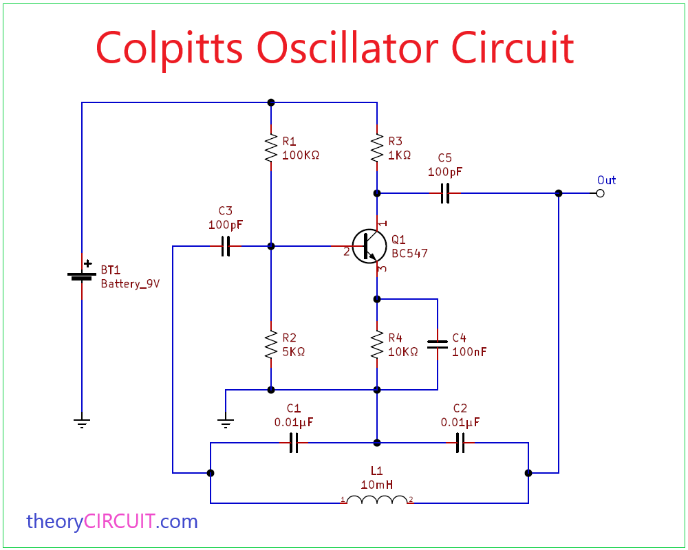
Colpitts Oscillator Circuit Circuit Diagram
Components Required
- Battery 9V
- Transistor BC547 (NPN)
- Resistor 100KΩ, 5KΩ, 1KΩ, 10KΩ
- Capacitor 0.01μF = 2, 100pF = 2
- Capacitor 100nF
- Inductor 10mH
Circuit Construction & Operation
In Colpitts Oscillator the tank circuit contains two Capacitors connected in series C1 and C2 then Inductor L1 Connected parallel to the tapped Capacitors. Transistor BC547 acts as a Common emitter amplifier and R1, R2 Resistors provides bias to CB terminals and BE terminals. Feedback path between collector and base terminal has tank circuit in its path.
When the supply is switched ON, capacitors C1 and C2 are charged. Then these capacitors discharge through coil L and so, initial oscillations are generated. The oscillations across C2 are applied to the base emitter junction of the transistor.This is amplified and available in the collector circuit. The amplified power from collector is applied to the tank circuit to meet out the losses during energy conversation between capacitors C1 and C2 and inductance L. The amount of feedback depends upon the value of capacitance C1 and C2. The transistor amplifier provides 180º phase shift and the capacitor feedback provides another 180º phase shift. Hence totally there will be a phase shift of 360º which provides positive feedback. Therefore, continuous undamped oscillations are generated.
Colpitts Oscillator circuit formula
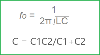
Where,
- L is inductor value of L1.
- C is the total value of capacitors C1 and C2 connected in series.
Colpitts oscillator circuit is used in signal generators and used in super heterodyne radio receivers as local oscillator and many low cost oscillator.
This circuit does not work. I found another on wiki and using the same components on the same board it works as stated.
As hfe varies perhaps you should state the required value for this design
Can I know what circuit you using?
Two faults, Biasing and drive to tank circuit.
Change R2 to 50k and R5 to 10k. The will make the collector sit at a DC average of 6.8V and its emitter sit at DC average of 2.2V.
The drive to the feed back tank circuit is too little as the value of C5 is too low. Replace C5 with 100nF and replace C3 with a short circuit (0 Ohms).
The output can be taken as shown but it is better to used another 100nF capacitor/100k resistor combination. Connect new C to collector and 100k rsistor to ground100k resistor to ground. Output from series junction of both. This change is because output loading can affect the DC bias via the inductors DC connection to the base.
Checked with simulation in TINA. output oscillates with distortion at about 22khz