Last Updated on March 16, 2024
DC-DC Boost converter circuit using MC34063A IC from Texas Instruments, the MC34063A series is a monolithic control circuit containing the primary functions required for DC to DC converters. Hence it requires minimum number of external components for step up, step down and voltage inverting operations.
A DC-DC boost converter is an electronic circuit that takes a lower DC voltage as input and increases it to a higher DC voltage at the output. It essentially “boosts” the voltage level, making it a crucial component in various electronic applications. The primary purpose of a boost converter is to address situations where the available voltage is insufficient for the requirements of a particular device or circuit. If you are using battery as a power source and it is limited to some voltage levels like 6V, 9V etc.., if your circuit elements need 12V or more then you don’t have to go for other power source, you can simply use this kind of DC-DC boost converter circuit to increase present power source to desired level and you can use both power supply.
Circuit Diagram
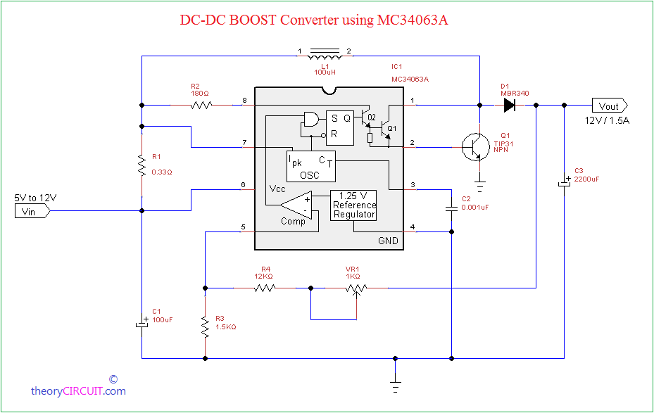
DC-DC Boost Converter using MC34063A Schematic
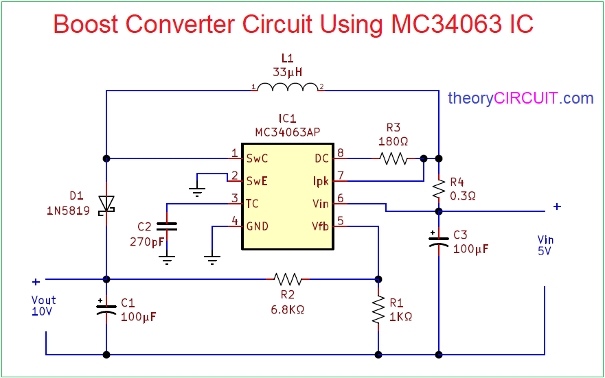
DC-DC Boost Converter using MC34063A Schematic – It will give 10 Volt output from 5 Volt DC input.
Construction and Working
This circuit is designed to give 12V/1.5A output from minimum 5V DC input main part of this step up DC-DC converter is IC MC34063A, it is capable of taking input from 3.0V to 40V and gives output current range upto 1.5A with Adjustable output Voltage and also it has current limiting possibility and low standby current.
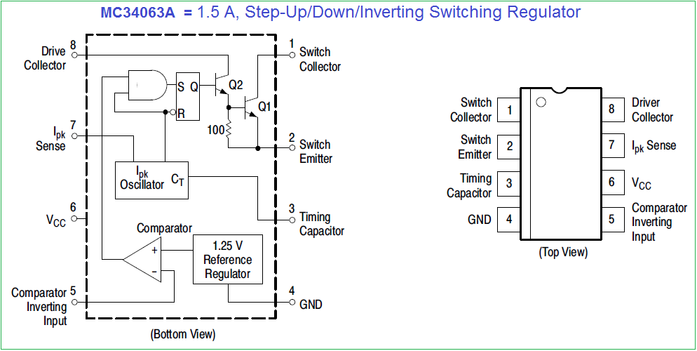
MC34063A Pinout
Value of R1 and R2 Resistors are responsible for internal oscillating frequency and VR1 is takes control on efficiency because it is connected between output and internal comparator.
Here L1 is 100µH or you can make core coil with 30 turns of 22 AWG, the MBR340 Schottky barrier rectifier gives pure DC at output. This circuit can be used for step up DC supply from batteries.
i tried this circuit but i get fixed output which is 11.1v, can you please explain more to me how it works?
thanks
Adjust the input Voltage to get Desired output. Some times This circuit Gives dropped voltage depends on external components.
giriş voltajı 12v, çıkış voltajı 24v 1,5a olması için degerler nasıl degiştirebilirm.?
MC34063A Serisi, DC-DC dönüştürücüler için gereken birincil işlevleri içeren monolitik bir kontrol devresidir. Bu cihazlar dahili sıcaklık kompanzasyonlu referans, karşılaştırıcı, aktif akım limit devreli kontrollü görev döngüsü osilatörü, sürücü ve yüksek akım çıkış anahtarından oluşur. Bu seri, minimum sayıda harici bileşenle Step-Down ve Step-Up ve Voltaj-Ters Çevirme uygulamalarına dahil edilmek üzere özel olarak tasarlanmıştır. Vout formülünü kullanın ve istenen çıkış voltajı için R1, R2’yi değiştirin.
On Q1 I missed the pull-down resistor at base so Q1 will safe turn off. Reduce C2 will increase switching frequency so you can reduce size for L1. TIP31 for Q1 looks like to small for 1.5A output current, Q1 should be switching 3 to 5 times more than output current. I though there were a lot of mistakes in this circut, you should calculate the correct values by using the equations given by datasheet from the MC34063