Last Updated on March 16, 2024
Variable Resistor or Potentiometer gives different range of Resistance value in circuit and used in many applications like volume control for Audio circuit, Television, Oscillators, Home Electrical appliance etc..,
This Article describes what is digital potentiometer? and How to interface with Arduino board.
What is digital Potentiometer?
A digital potentiometer comes in a integrated circuit (IC) package and it mimics the physical mechanical variable resistor or potentiometer with the help of control signals.
Digital Potentiometer MCP41xx
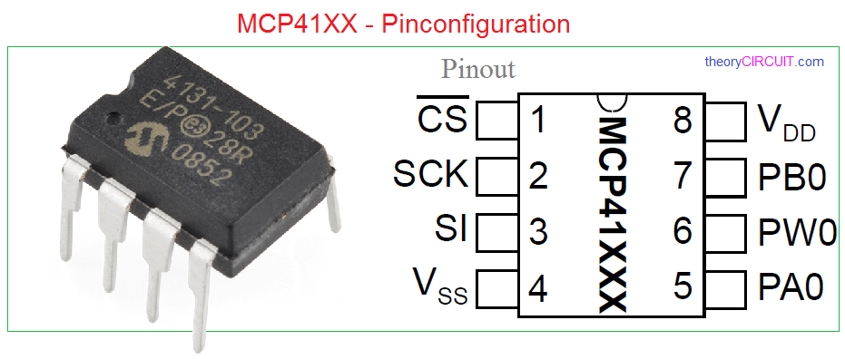
The MCP41XX is a single-channel digital potentiometer device and is offered in an 8-pin PDIP or SOIC package by microchip company, the MCP41XX device is 256 – position, digital potentiometers available in 10 kΩ, 50 kΩ and 100 kΩ resistance versions. There is MCP42XXX available to provide two channel digital potentiometers. The wiper position of the MCP41XXX/42XXX varies linearly and is controlled via an industry-standard SPI interface. [find more on datasheet].
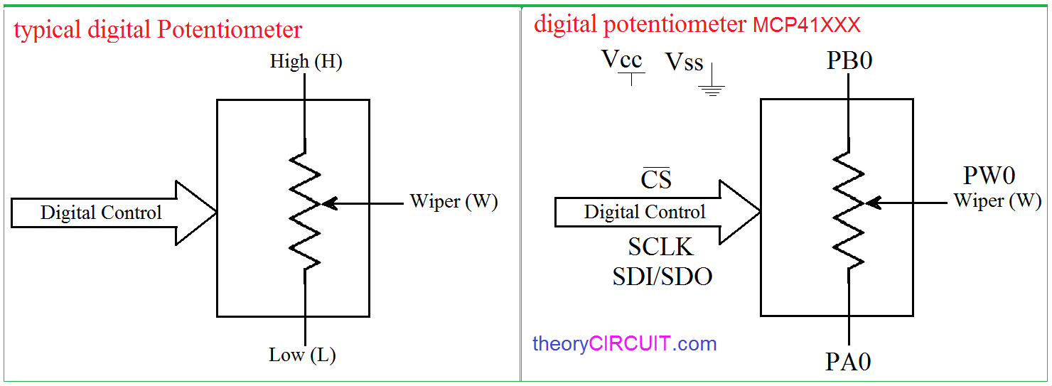
Typical digital potentiometer have High resistance value pin, Low resistance value pin and Wiper for variable terminal and this wiper output is controlled by the digital control pins. Here function diagram of MCP41xx is given with comparison, PB0 represents High, PA0 represents Low and PW0 represents wiper terminals. By varying the control signals we can get different resistance value at wiper (PW0) terminal.
Arduino Interfacing to digipot MCP41xx
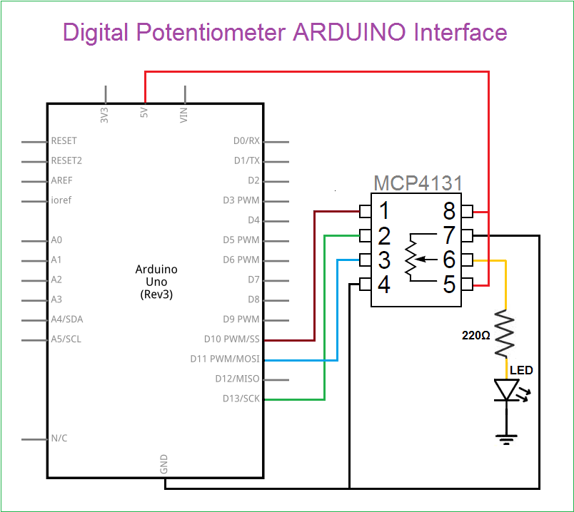
In this interfacing circuit an LED is taken as target device and bias to that LED is given followed by digital potentiometer and control signals are driven by the Arduino controller. This circuit gives different intensity level LED light output by varying the Resistance value inside the digital potentiometer MCP41xx.
Arduino Code
#include <SPI.h>

byte address = 0x00;
int CS= 10;

void setup()
{
pinMode (CS, OUTPUT);
SPI.begin();
}

void loop()
{
for (int i = 0; i <= 128; i++)
{
digitalPotWrite(i);
delay(10);
}
delay(500);
for (int i = 128; i >= 0; i--)
{
digitalPotWrite(i);
delay(10);
}
}

int digitalPotWrite(int value)
{
digitalWrite(CS, LOW);
SPI.transfer(address);
SPI.transfer(value);
digitalWrite(CS, HIGH);
}
Would this digital potentiometer also work without connecting 5V to terminal 5? So that the potentiometer is not connected to power just like an expression pedal? I’m trying to digitally control a potentiometer and then use this to control the expression input of a guitar pedal.
Your expression pedal would still be using voltage across the POT that is in it. Typically most use a 9V battery to operate (depending on circuitry the voltage may be dropped to 5V across the POT but could be higher). Use a multimeter to figure out what voltage is across the POT and if it is indeed 5V you could easily connect the V+ on your POT to pin 5, the wiper on the pot to pin 6 and pin 7 to ground. But you would have to take the current pot out of circuit (either permanently or with a switch switching the wiper pin from digital to analog) otherwise you have two POT’s trying to control the circuit which is not good.