Last Updated on March 16, 2024
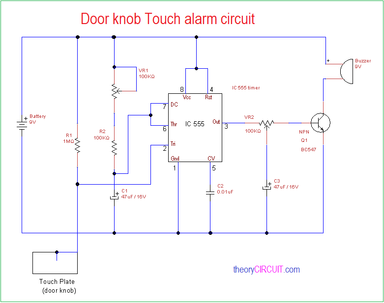
Simple Door Knob Touch Alarm Circuit is constructed by using timer IC 555 and few easily available components. This circuit will give alert sound when some one touch the door knob, It is suitable for simple security applications. To implement this circuit your door knob must be a conducting material.
Use the door knob as a touch plate and it can be act as trigger input to the timer IC. You can use DC power supply source or 9 Volt battery to power this circuit.
Circuit Diagram
Components Required
- Timer IC 555
- Buzzer 9V
- Transistor BC547
- Variable Resistor 100KΩ =2
- Resistor 100KΩ, 1MΩ
- Capacitor 47μF / 16V =2
- Capacitor 0.01μF
- Battery 9V
Construction & Working
In this Door Knob Touch Alarm Circuit IC 555 employed as a monostable multivibrator and it produce square pulse at output when the trigger pin gets input and the output pulse duty cycle & duration can be varied by using variable Resistor VR1.
Output pulse from the timer IC555 given to the transistor base through variable Resistor VR2, here C3 capacitor connected to the variable pin of VR2 and this capacitor keeps transistor Q1 turn ON for long duration.
When the door knob touched by a person, it will triggers the timer IC 555 and depends on the timing Resistor and timing Capacitor value timer IC starts oscillating Square pulse and this pulse drives transistor Q1. A Buzzer is connected to the Q1 collector and it will get bias whe the Q1 gets turn ON.
This circuit will provides a short duration alarm sound and it can be increased or decreased by the timing components value, you can connect Relay at the output of timer IC and control any target electrical device.