Last Updated on March 16, 2024
If you want to Protect some door from unwanted access then you can use this simple Door Open Alarm circuit using Reed switch.
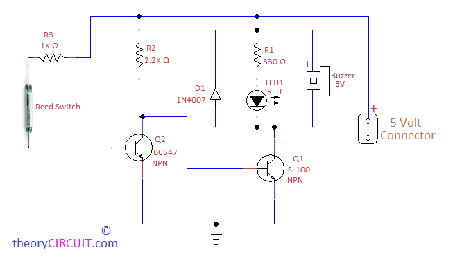
Circuit Diagram
Construction and Working
Here Reed switch acts as a Sensor to detect the door position (close/open). The Reed switch is a small device and contains two ferrous materials inside.
When this device exposed to the Magnetic field then ferrous materials inside 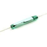 reed switch pull together and switch closes. When there is no magnetic field then ferrous materials separate and switch open. By the way this element reacts as a non contact switch in a circuit, and also it can carry upto 1.2A current.
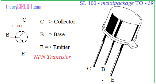
This Alarm circuit constructed by using two familiar transistors BC547 and SL100. Here SL100 NPN transistor reacts as a Switching device to turn ON and OFF buzzer, 5Volt DC supply directly fed into Reed switch through R3, another terminal of reed switch given to the Q2 transistor base. The Q1 transistor base terminal directly connected to the Q2 transistor collector.
Alarm Position
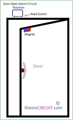
When the door is closed, due to the near magnetic field reed switch close and conducts DC bias to Q2 base and Q2 gets turn ON then grounds the supply. Hence there is no input to the Q1 base so Q1 stays in turn OFF condition. When door open magnet attached with door moves far away from reed switch and reed switch becomes open, there is no bias in Q2 base hence Q2 turn OFF, bias supply through R2 Resistor now flows towards Q1 base and makes it turn ON due to the conduction in Q1 transistor buzzer connected to bias and produce alert sound.
Reference
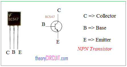
Transistor Pinout
hello sir, how cand I add a delay time for this circuit? I want to open the door and only after two minutes to start the buzzer. Thank you!
Simply use time delay circuit.
Can you explain the purpose of the diode? It is not regulating any voltage and don’t see it protecting a component of extra voltage or current. It seems like it doesn’t need to be there and pointless, but surely it does so that’s why I am asking
Hello sir i want a picture of this project on bread board