Last Updated on March 16, 2024
When we use ICs in the circuit some times we cannot get desired output, then we have to check each components in the circuit. Testing Integrated Circuit is much complex than other components, in order to check operational amplifier IC that is 741 we need to put in working application to test it. Here is the easy method to check the op-amp IC 741, this simple IC 741 tester circuit can be constructed with few resistors, a capacitor and LEDs.
About IC 741
IC 741 is the most used operational amplifier sometimes called as op-amp IC, this IC is Widely used in various electronic circuits, the 741 op-amp is known for its reliability, versatility and easy to use characteristics. This 741 IC is designed to amplify voltage signals and it is characterized by high input impedance, low output impedance, and high output gain characteristics. IC 741 is widely used in applications such as signal processing, audio amplification, and instrumentation amplifiers. As electronic engineers we know op-amp have enormous applications than mentioned here. The 741 IC’s straightforward design and compatibility with a range of electronic systems have contributed to its enduring popularity in the field of electronic product design and circuitry.
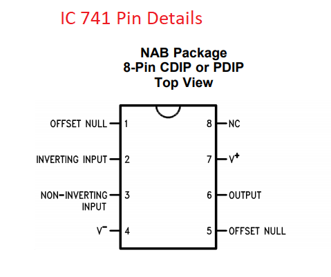
| Pin No. | Pin Name | Pin Description |
| 1 | OFFSET NULL | Offset null pin used to eliminate the offset voltage and balance the input voltages. |
| 2 | INVERTING INPUT | Inverting signal input |
| 3 | NONINVERTING INPUT | Noninverting signal inpu |
| 4 | V– | Negative supply voltage |
| 5 | OFFSET NULL | Offset null pin used to eliminate the offset voltage and balance the input voltages. |
| 6 | OUTPUT | Amplified signal output |
| 7 | V+ | Positive supply voltage |
| 8 | NC | No Connect, should be left Open and floating |
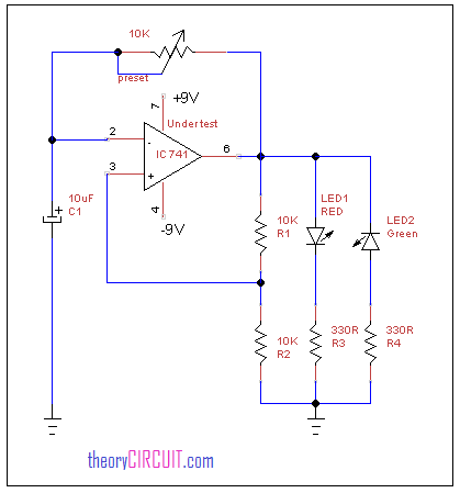
Circuit diagram for IC 741 tester
Construction and working
IC 741 Operational Amplifier can be configured to operate as a pulse generator with the RC external components. This circuit is designed to test the unknown 741 ICs hence use 8 pin dip socket so that you can insert and remove testing 741 IC, To set up the 741 IC as a testing pulse generator, you typically use it in an astable multivibrator configuration. This involves connecting resistors and capacitors to the inverting and non-inverting inputs of the op-amp. In this configuration C1 capacitor charges and discharges through the preset resistor and creating a square wave pulse output. The charging and discharging times are determined by the values of the preset resistor and capacitor C1 used. By adjusting these components, you can control the frequency and duty cycle of the generated pulses.
This circuit constructed with two indication LEDs and variable resistor with capacitor, by placing op-amp in this circuit it becomes as a pulse generator. If the testing IC is good, the two LED glows alternatively.
If the LEDs not glowing alternatively means the testing IC might damaged or faulty one.