Last Updated on March 16, 2024
Need to design a simple and useful security alarm then you can refer this IR Based security Alarm using 555 timer prototype. In this circuit IR (Infra Red) beam acts as a Invisible fence, whenever the IR Rays are blocked then this circuit will produce alert sound through loud speaker.
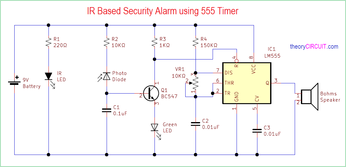
This circuit has two stage, first one is IR emitter & IR receiver stage then second one is Astable Multivibrator timer circuit, Here the timer circuit Reset pin is Accessed by the IR stage hence the multivibrator oscillates when the IR rays blocked.
Circuit Diagram
The Above circuit have some Error and it could continuously produce buzzer sound even the IR LED placed directly to photodiode. Instead of above use the following circuit for to make IR Based Security Alarm using 555 Timer.
Components Required
- IR LED Photo diode pair
- IC 555
- Loud speaker 8Ω
- Resistors 220Ω, 10KΩ, 1KΩ, 150KΩ each one
- Variable Resistor 10KΩ
- LED green
- Capacitors 0.1μF = 2, 0.01μF
- Transistor BC547
- Battery 9V
Construction & Working
Basic operation of this circuit is very simple, Timer IC 555 configured in Astable Multivibrator mode but the Reset pin is connected to the Collector terminal of Transistor Q1. This Q1 gets base supply from the photo diode. As we know photo diode in reverse bias conducts current flow when it receives Infra Red signal and some strong visible light.
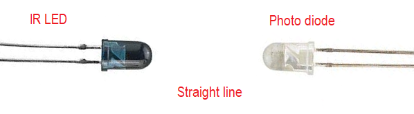
The IR LED gives IR rays continuously and it should be placed towards photo diode in straight line.
So the photo diode conducts current and gives supply to the base terminal of Q1, due to that transistor stays in ON condition and gives negative or ground supply to the Reset pin of timer and keeps timer ic in reset condition. when the IR beam is interrupted in any way then the photo diode stops conducting current and hence there is no supply to base terminal of Q1 then it become turn OFF. So the Reset pin gets positive supply and Timer IC starts to Oscillate Square wave and produce alert sound through the speaker connected at output pin.
Here the timer IC output frequency is depends on the timer Resistor R4, VR1 and timer capacitor C2, by varying VR1 we can get different level output sound at loud speaker. Want to know how the Astable Multivibrator works?
Even simple Circuit to try.
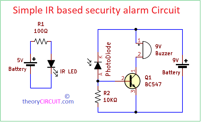
If you are interested, try this simple ir security alarm circuit by using only one transistor and buzzer. It is compact and fit in small places, where you need alert sound for blocking or obstacle.
Hi, I have designed this circuit on breadboard. But I got an issue.When I wire 9V, the circuit is always in alarm mode. The green led is always on and the speaker always makes noise. Where is the problem? Which wire or which component ?
In this Circuit IR and Photodiode are need to be placed in straight line.
Before you apply power supply to this circuit check the transistor BC547 Terminal and Variable Resistor, As i read your comment i came to know you are prototyping this circuit in breadboard so make sure all connections and nodes are perfectly connected and cross check with the schematic. Hope you will get proper output.