Last Updated on March 16, 2024
LASER is Light Amplification by Stimulated Emission of Radiation and laser diodes are widely used in different domain applications, it gives focused light ray in visible spectrum and laser diodes will perform good in regulated constant current. Depends on application laser chosen at different range nm (nano meter) wavelength and watts.
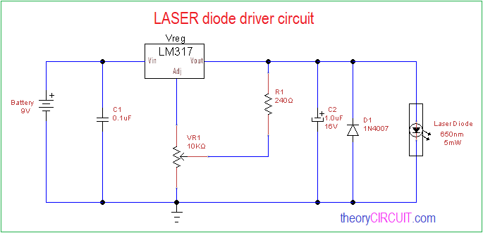
In this project LASER diode driver circuit is developed with adjustable voltage regulator LM317 to drive red color 650nm 50mW laser diode. This circuit is suitable for constant and continuous glowing of laser diode. We can adjust the intensity of light by this circuit.
Circuit Diagram
Components Required
- Bread board
- Laser Diode 650nm, 5mW
- IC LM317
- Capacitor 0.1uF
- Capacitor 1.0uF/16V
- Variable resistor 10KΩ
- Resistor 240Ω
- Diode 1N4007
- Battery 9V
Construction & Working
LASER Diode
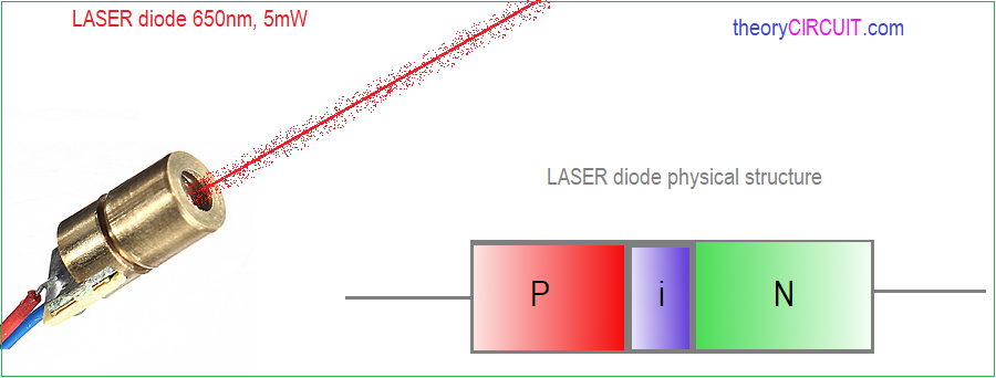
Laser diodes are made as PiN semiconductor that is P type semiconductor and N type semiconductor are separated by i intrinsic layer, depends on the intrinsic semiconductor layer material laser diode’s wave length and color varies. The P type layer concentrated with majority holes & minority electrons then N type layer concentrated with majority electrons & minority holes. Some high power laser diodes manufactured with heat sink to avoid thermal run away.
This circuit begins with filter capacitor C1 0.1uF and it is responsible for filtering high frequency ripples in DC supply. Adjustable voltage regulator IC LM317 biased with ground through variable resistor VR1 and variable output terminal of VR1 is connected at the output pin of IC LM317 through R1 resistor. By changing the VR1 Resistor we can adjust the regulator ICs output voltage. The capacitor C2 balance the output voltage given to laser diode and D1 avoids reverse polarity bias to the Laser diode.
When we apply power supply (here 9V battery) Regulated constant voltage and current reaches the laser diode and drives it to give maximum output. Place Laser diode in this circuit with caution to its polarity, wavelength and power.
Note
Basic Laser & Higher class lasers are dangerous to naked eyes and skin do not expose in its path.
Can you help me design circuits to maximize electron density at a given potential? I want to minimize resistance in the circuit. Zero would be ideal. Where should I start?
Hi.Out of curiosity I checked the calculations of resistors R1 and R2 to evaluate the output voltage and a voltage of about 50V came out. Where did I go wrong?
Just so you know 99.9% of those small 5mw lasers actually have a very small resistor in series with the laser. Technically, you could drive it off of a battery of accurate voltage. I thought they were without drivers of any sort and then I looked closely and realized it had the current limiting resistor. Oh well, I bet that help a lot of people with successfully driving this little laser.
Hi would this work for a 5W 350nm blue laser? 4.3V at 3A? thank you!
This Circuit designed with LM317 and which is capable of handling 1.5A output current only. Somehow 5W 350nm blue laser work but to get full efficient blue laser light you need to use voltage regulator LM350T 3A instead of LM317. (lasers are Very dangerous handle with extreme care and always use laser protective eye glass)