Last Updated on August 13, 2021
We bring to you the best simple circuits which will gives output without any boring. Beginner must try top five hobby circuits from theorycircuit.com
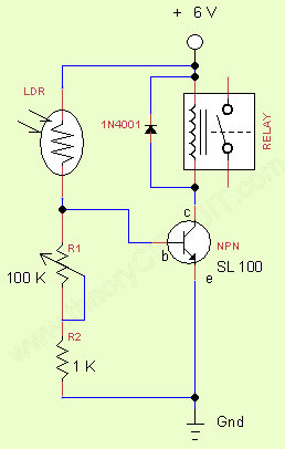
This circuit reacts as a light activated relay, we can use this circuit as a switch to activate any work when light is appeared. For an example we can connect garden lamp into the relay (in normally close pin) whenever the sunlight appears the relay contact moves to (N/o) hence the lamp will automatically switched off.
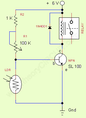
Dark Activated Relay:
We can use this circuit as a switch to activate any work when light is disturbed or the darkness appeared. By changing the value of R1 we can obtain different level of sensitivity to darkness.
Components List
| S.No | Name | Quantity |
| 1. | Relay 6V | 1 |
| 2. | Transistor SL 100 | 1 |
| 3. | LDR small size | 1 |
| 4. | Diode 1N4001 Resistor 1K Trimpot 100K |
1 1 1 |
2. Touch alarm
IC 555 used in many simple and useful circuits, every electronics hobbyist may surely tried IC 555 at least once while they learn electronics circuit making. Here the circuit is senses human touch and gives louder alert through buzzer.
This touch alarm circuit uses 9volt bias supply hence we can use general purpose 9volt battery for portable applications. Here Resistors R3,R4 and Capacitor C3 reacts as a Timing components, by varying R4 value we can obtain different timing output at the output pin 3. The SL100 transistor is reacts as a switch to connect buzzer with bias. Resistor R1 and capacitor C1 changes output wave shape as ramp depends on R1 resistor value the buzzer will produce different type of alarm sounds when the touch plate sense.
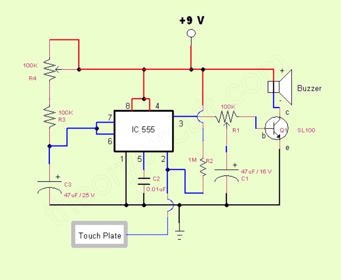
Components List
| S.No | Name | Quantity |
| 1. | IC 555 | 1 |
| 2. | Buzzer 9v | 1 |
| 3. | Transistor SL100 | 1 |
| 4. | Resistor 100K Resistor 1M Trimpot 100K Capacitor 47uF Capacitor 0.01uF metal touch plate(coin) |
1 1 2 2 1 1 |
3. Variable Regulated Power Supply IC LM317
Variable Regulated power supply is very much essential for to test electronic circuits. Here is the simple circuit with IC LM317 gives variable DC voltage ranges from 1 to 30 Volts. The resistor R2 is the control for variable DC Voltage output.
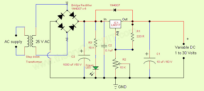
Components List
| S.No | Name | Quantity |
| 1. | Step down Transformer (230 V to 25 V) | 1 |
| 2. | Diode 1N4007 | 5 |
| 3. | Resistor 10K Resistor 220R Trimpot 10K LED Green Capacitor 1000uF/50V Capacitor 10uF/50V Capacitor 0.1uF |
1 1 1 1 1 1 1 |
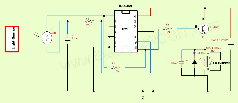
4. Light Fence
This circuit can be used for security purpose, by implementing light fence at the entrance gate or entry door we can get notified before the person knock the door. Use white LED biased with 220 &Omega 3 Volt battery for light source.
Components List
| S.No | Name | Quantity |
| 1. | IC 4069 | 1 |
| 2. | LDR medium size | 1 |
| 3. | Relay 9Volt | 1 |
| 4. | Light source (white LED) | as required |
| 5. | Transistor 2N4401 | 1 |
| 6. | Resistor 100K Resistor 10K Capacitor 1 uF/20V Capacitor 100nF Diode 1N4004 |
1 2 1 1 1 |
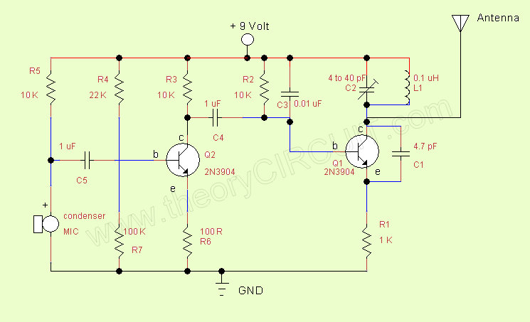
5. Simple FM transmitter
Frequency Modulation reaches several meters to kilo meter with low power transmitter circuit. Here two transistor based FM circuit diagram given for hobby use. The condenser mic converts voice signal into audio signal and transistor Q2 amplifies the audio (message) signal. The Q1 transistor is produces Carrier frequency. Amplified audio(message) from Q2 transistor is directly applied to the Q1 transistor base terminal. Hence frequency of carrier signal varies according to the audio (message) signal. By the way we get FM wave from the collector terminal of Q1 transistor. By using lengthy monopole antenna we can transmit FM wave up to several kilometres.
(always tune the FM Carrier frequency in the transmitter to a license free band)
Components List
| S.No | Name | Quantity |
| 1. | Transistor 2N3904 | 2 |
| 2. | Condenser MIC | 1 |
| 3. | Gang capacitor (variable capacitor) 4 to 40pF | 1 |
| 4. | Capacitor 1 &uF (disc type) | 2 |
| 5. | Capacitor 0.01uF Capacitor 4.7pF |
1 1 |
| 6. | Resistor 10K Resistor 22K Resistor 100K Resistor 100R Resistor 1K |
3 1 1 1 1 |
| 7. | Inductor 0.1uH | 1 |