Last Updated on March 16, 2024
This Over voltage protection switch circuit constructed with TL431 adjustable shunt regulator and MOSFET.
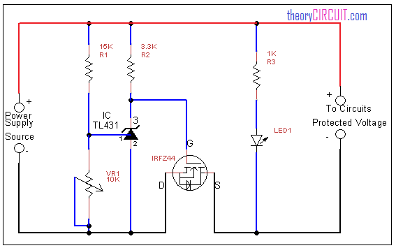
Circuit diagram for over voltage protection switch
Construction and Working
The TL431 device has three terminals and main application of this device is adjustable shunt regulation. The reference regulating voltage can be given through cathode and reference pin. Here the VR1 variable resistor decides the regulation range, by changing it we can get different range of regulating voltage.
The LED1 gives status about the output voltage presence if the input voltage to this circuit goes beyond the limit that is over voltage means the TL 431 blocks the voltage through MOSFET hence the circuit connected with this setup protected from over voltage.
You can get datasheet of IC TL431 here.
Hello,
this the first time I try an overvoltage protection circuit. This one works just fine but I found an error in the schematic about the Mosfet Pinout. Drain and Source pin need to be switched!
Regards,
—
Philippe
Yes you are right. Drain and source pin should be switched.
there is another issue… this is a series and not a parallel (crowbar) circuit. moreover it only monitors supply side voltage, not load side. this means if somehow higher voltage is introduced to the load itself (without affecting supply) this circuit would not sense the change and it would not protect the load.
This circuit designed for the load circuit which requires over voltage protection and hence this circuit is most suitable for passive loads.