Last Updated on March 16, 2024
PIR sensor (Passive Infrared sensor) widely used in motion detection applications and security based applications, the following project is a burglar alarm circuit by using PIR sensor and three siren sound generator IC UM3561.
We should pay more attention to our security, here burglar alarm designed to detect intrusion and unauthorized entry and it is very useful to protect our living space, house, and office from theft. This PIR burglar alarm circuit provides sound alert against unauthorized entry or movements.
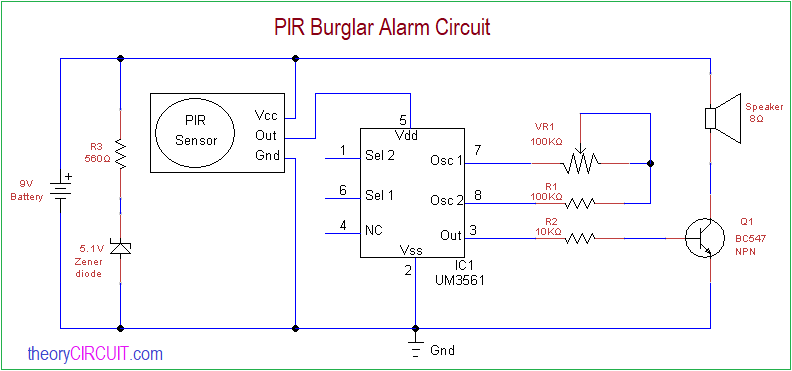
Circuit Diagram
Components Required
- PIR sensor
- I UM3561
- Speaker 8Ω
- Zener diode (5.1V)
- Resistor 560Ω,100KΩ, 10KΩ
- Variable Resistor 100KΩ
- Transistor BC547
- Battery 9V
- Bread board
- Connecting wires
Construction & Working
Main part of this circuit is PIR sensor, it can detect the Infrared (IR) light radiation emitted from person or object and gives logical output signal. The UM3561 is responsible to detect and generate siren sound.
9V battery provides power supply to this circuit, a 5.1V zener diode placed across the battery supply and provides regulated power supply to the PIR sensor, output of PIR sensor (3.3V) is connected to the Vdd pin 5 of UM3561 and when ever the PIR sensor detects motion then the UM3561 gets supply and starts to give siren sound through speaker.
PIR Sensor
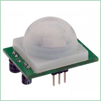
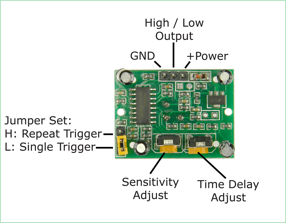
PIR sensor comes with breakout board gives you options to control trigger, sensitivity adjust and time delay adjust. It uses only three pins one is Vcc (+5V) and GND power pins then Output pin, it gives High during IR presence (3.3V) else Low output (0) depends on the IR detection.
Further: