Last Updated on March 16, 2024
For a voltage sensitive load or electric element we need to provide regulated voltage. In some case applied voltage level may increase beyond maximum voltage range of load, hence we need to make a setup to protect load from high voltage. Here simple overvoltage protection circuit designed by using zener diode and transistors.
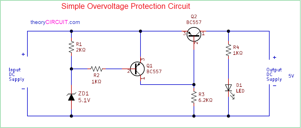
This Circuit Cutoffs the supply to load when the input voltage exceeds the chosen Zener diode regulating voltage, here Zener diode breakdown voltage is the boundary of voltage limit to the load., We have 5V load and hence we have used 5.1V Zener diode, you can choose Zener diode voltage range depends on your load or device voltage range.
Circuit Diagram
Components Required
- Zener diode 5.1V
- Transistor BC557 PNP = 2
- LED
- Resistor 2KΩ, 6.2KΩ each one
- Resistor 1KΩ = 2
Circuit Construction & Working
This simple overvoltage protection circuit is easy to construct with few easily available components. To start this circuit you need to decide the regulating voltage range of zener diode based on load element and then connect two PNP transistors with specific voltage rage. In this circuit we have used two BC557 PNP transistors as a switch. LED near to the output indicates the presence of output voltage within the allowed voltage range.
When we apply DC power supply to this circuit, reverse biased zener diode acts as voltage regulator and regulated voltage flows through Q1 transistor and to the Q2 transistor base terminal, here Q2 transistor allows voltage from input source to load when under 5V. If the input source voltage increases beyond 5V then Q2 transistor and Q1 transistor disconnects load (Q1 and Q2 goes to OFF condition).
Use Q1 and Q2 switching transistor based on load element voltage and current ratings. This circuit design protects load from limited over voltage and has moderate current flow limiting. Use this circuit design under 25V load. For overvoltage protection below 3.3V and above 25V use Specific integrated circuit (IC) for better results.
I don’t think this circuit would work. Doing circuit simulation also shows it won’t work.
Zender diode would cap the voltage 5.1v, it will not drain it all.
For example imagine input voltage is 7v, The point between R1 and ZD1 would be 5.1v not 0v.
So the transistor Qt would totally turn on allowing current to flow freely through the load.
Perhaps putting R1 instead of ZD1 and ZD1 instead of R1, would provide some protection
Transistors Q1 and Q2 controls and suppress over voltage and current but this circuit has some max VI limitations.
Explanation of the circuit appears incorrect. Say with a 10V input, ZD1 clamps the voltage at the base of Q1 at 5.1V. This turns Q1 ON (emitter base jucntion forward biassed) and so about 10V appears at the base of Q2. This turns Q2 off and protects the load.
If the input voltage Vi rises beyond 10V or so, then Q1’s V_eb will exceed BC557’s Absolute Maximum Rating of 5.0V.