Last Updated on March 16, 2024
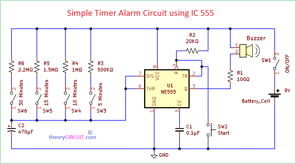
Are you Planning to Construct useful Standalone Timer Alarm Circuit? Then you are at right place. We don’t need Expensive Microcontrollers, Development boards or Complex circuits for to build robust time alarm. Here Very easy and Simple Alarm Circuit using Timer IC 555 constructed by using few inexpensive components. This circuit act as short duration timer and alarm, it can count and give alarm buzzer sound for four different timing intervals that is 5 minutes,10 minutes,15 minutes and 30 minutes. If you good at tuning potentiometer then you can use 1MΩ Variable resistor instead of (R3, R4, R5 and R6) for variable time setting.
We know IC 555 is generally termed as Timer and this circuit is most suitable design for 555. Choose any output actuators depends on your need here we used Simple 9V Buzzer as a output device. This will produce beep sound when the timer IC output goes to LOW after counting selected time.
Circuit Diagram
Components Required
- Timer IC NE555P – 1
- 9V Buzzer -1
- Battery 9V – 1
- Push button switch – 1
- SPST ON/OFF Switch – 5
- Capacitor 470μF/25V, 0.1μF – each 1
- Resistors 100Ω, 20KΩ, 500KΩ, 1MΩ, 1.5MΩ, 2.2MΩ – each 1
Construction & Working
Before getting into the Construction and Working of Timer Alarm Circuit using IC 555 let us see What is Timer IC and its basic operation.
IC 555
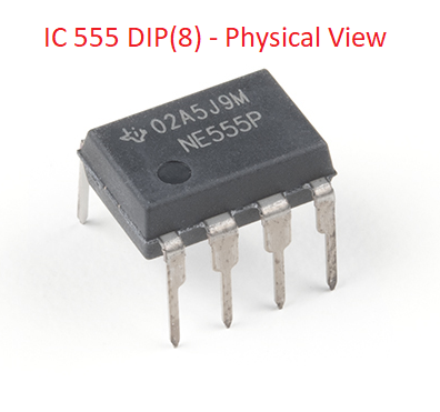
Most useful and Most Utilized IC in analog electronics as well as digital electronics is IC 555, Which is Designed by Hans R. Camenzind in 1972, Due to its internal voltage divider setup its been called as 555 (not sure). This IC application expands from basic timers and pulse generators to more complex Oscillators and Pulse Width Modulation (PWM) due to its adaptability and ease of use.
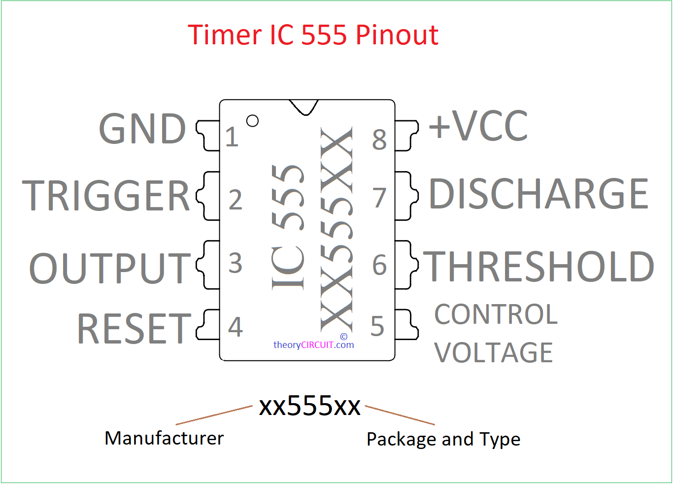
IC 555 Pinout
| Pin Number, Name | Description |
| 1, GND | Ground supply |
| 2, TRIGGER | External trigger pulse applied to this pin |
| 3, OUTPUT | Output Pin |
| 4, RESET | -Ve pulse applied to this pin to disable or reset the time |
| 5, CONTROL VOLTAGE | Controls the threshold and trigger levels |
| 6, THRESHOLD | Compares the voltage applied to the terminal with a reference voltage of 2/3 Vcc. |
| 7, DISCHARGE | Open collector output which discharges a capacitor between intervals. toggles the output When 2/3 Vcc. |
| 8, +VCC | Positive supply for IC |
IC 555 Internal Blocks
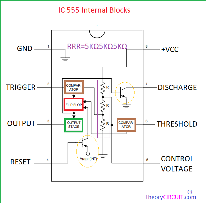
By understanding the internal Blocks of Timer IC 555 we can easily understand its operation. 555 Timer IC contains Two Voltage Comparators, an SR Flip Flop, a discharge transistor and a Resistor divider network. Operation of these internal bloks are depends on the Charging and Discharging of an External capacitor through External Resistors (Timing elements). By changing the Value of Timing elements we can control the timing intervals of this IC.
Modes of Operation
This Timer operates in three modes, 1. Astable 2. Monostable 3. Bistable in all modes IC 555 Oscillates pulse depends on the timing elements. For Astable mode continuously Oscillates square pulse at chosen duty cycle. For Monostable only one pulse when ever the trigger input applied. For Bistable timer ic oscillates two stable state output when the trigger input applied.
Operation of Simple Timer Alarm Circuit using IC 555
Timing limits are depends on Resistors R3, R4, R5, R6 and Capacitor C2 because the IC 555 is configured in monostable multivibrator mode and the above stated elements are acts as a timing elements. 9V Buzzer is connected with the output pin through R1 Resistor and another terminal is connected to the positive supply. One push button switch is connected with the trigger pin, when ever this button pressed then the IC 555 Starts to Oscillate one pulse during depends on the chosen timing element. Time period of the output pulse can be calculated as.
T = 1.1*R1*C1
This monostable multivibrator formula can be rewritten depends on our circuit,
T = 1.1*(either R3 or R4 or R5 or R6)*C2
For an example we choose R3 as timing resistor,
T = 1.1*R3*C2
T = 1.1*500000*0.00047 = 258.5 Seconds
258.5/60 = 4.3 Minutes
This is the timing level that is taken by timing capacitor (C2) to get Charge 2/3 level of Vcc after getting trigger input, after C2 reaching this level Discharge pin changes the output state high to low during this LOW output buzzer starts to produce beep sound. During the output pulse time (HIGH) there is no buzzer sound.