Last Updated on March 16, 2024
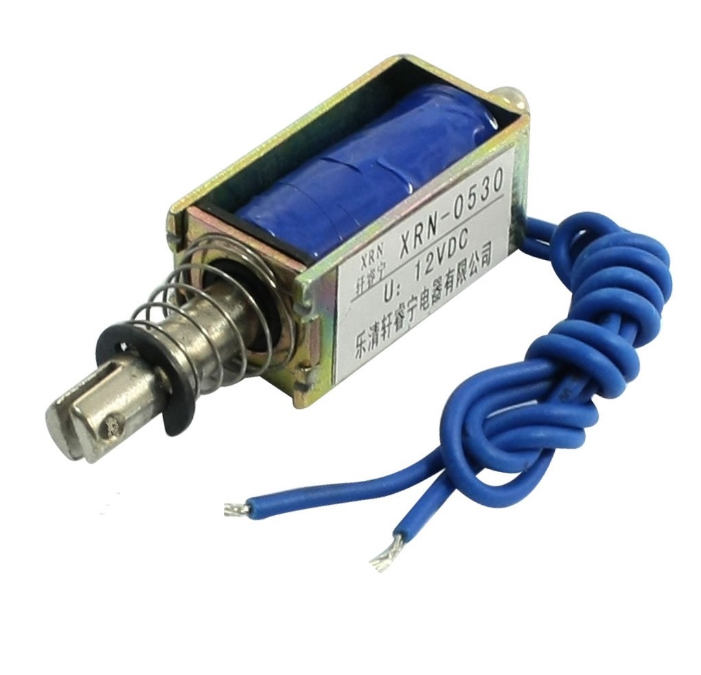
We know Solenoid is an electromagnetic device used to convert electric supply into linear motion by magnetic field. Many Solenoid device requires Regulated DC supply with constant current Due to the presence of electromagnetic coil and mechanical parts. Here simple solenoid driver circuit designed by using single NPN transistor.
A 12V Solenoid device is used here and it is driven by NPN transistor TIP120. This transistor gives better switch response at high voltage and current. Refer datasheet of TIP120 for technical details.
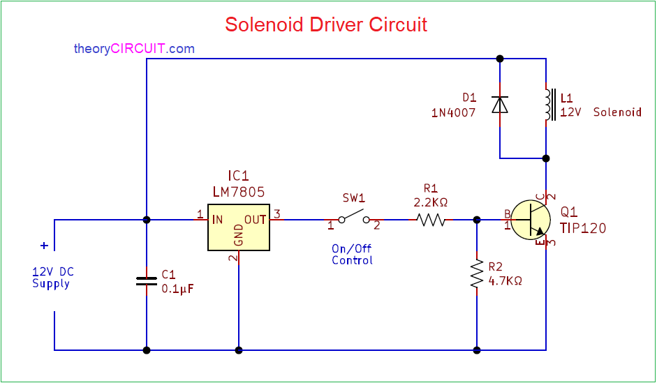
Circuit Diagram
Components Required
- 12V Solenoid
- Transistor TIP120 (NPN)
- Positive Voltage Regulator IC 7805
- Diode 1N4007
- Capacitor 0.1µF
- Resistor 2.2KΩ, 4.7KΩ each one
- On / Off switch
Construction & Working
By using few easily available components we can build this simple solenoid driver circuit. Transistor TIP120 requires minimum base voltage hence voltage regulator IC 7805 used to regulated the input DC voltage. Input supply 12V is directly applied to the solenoid device and another end terminal of solenoid is connected with TIP120 transistor collector terminal.
Regulator output is connected with base of Q1 through On / Off control switch. When the switch is in Off condition then Q1 transistor stays in OFF condition and solenoid can not get supply. When the switch is in On condition then Q1 transistor becomes ON state due to the base emitter voltage and solenoid coil gets supply and then becomes electromagnet then mechanical lever feels linear motion.
By using this simple solenoid driver circuit we can control current and voltage flow in the solenoid device. Solenoid devices are widely used in different industries, starting from simple locking devices, Automotive gear box, air conditioner, clamping device, medical equipment, agricultural systems, solenoid valves etc..,
Dera
Please help to me we have one caterpillar excavetor it has fuel injector pump shut of solenoyid ,i will explane how it’s work ,this solenoyid always in start position(that mean injector pump ready to start the matchine) when the ignition switch on and then we can start the machine ,if we of the ignition switch few second we need to get power to solenoyid and agine that power nedd to cut when the power is cut solenoyid will be come agine start position ,please give me some electronic drowing