Last Updated on March 16, 2024
This simple circuit can be used to check the crystal element whether it is working or not working. Many circuit uses crystal as a important component to oscillate signals, these signal are main requirement for other device in the circuit, if the crystal got damaged means we can not easily test the crystal without any oscillator circuit, to avoid this situation here we given simple crystal tester circuit using two transistors.
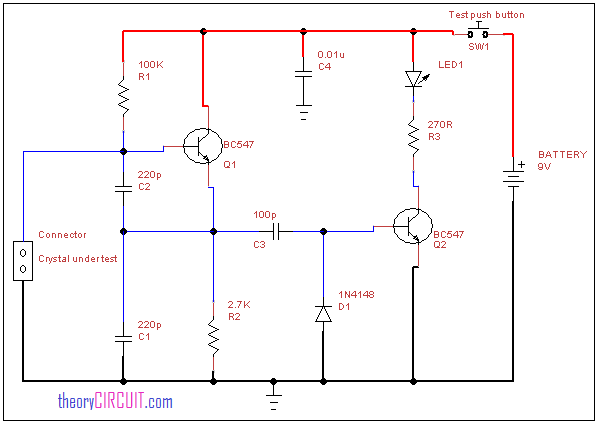
Circuit diagram for crystal tester
Components List
- Transistor BC547 = 2
- LED
- Diode 1N4148
- Resistor 100KΩ, 2.7KΩ, 270Ω
- Capacitor 220pF=2, 100pF, 0.01μF
Construction and Working
We know Crystal Oscillators are tiny yet powerful components and the heartbeat of many electronic devices, providing precise and stable frequency signals. Crystal oscillators are commonly used in microcontrollers, communication systems, and various embedded electronics applications. It comes in different frequency range and packages. This circuit helps to test two terminal through hole crystal oscillator devices.
When an electric field is applied to the crystal device then it vibrates mechanically at a specific frequency determined by its physical dimensions and shape. This mechanical resonance is then converted into an electrical signal that is oscillating signal. In this circuit two BC547 transistors are connected together with capacitor c2 and this base terminals are works as a test terminal for crystal, the Q2 transistor drives LED1, if the LED glows then the crystal under test is working if the LED not glowing means the crystal might damaged or faulty one, this circuit can be powered by 9 volt battery.
why we are using capacitor c1,c2,c4 and resistor r1 in the crystal tester circuit
As a Oscillating Elements.