Last Updated on March 16, 2024
This simple circuit helps to make louder horn for vehicle or alarm, this circuit constructed by two timer IC555 and the output sound produced through 8Ω loud speaker.
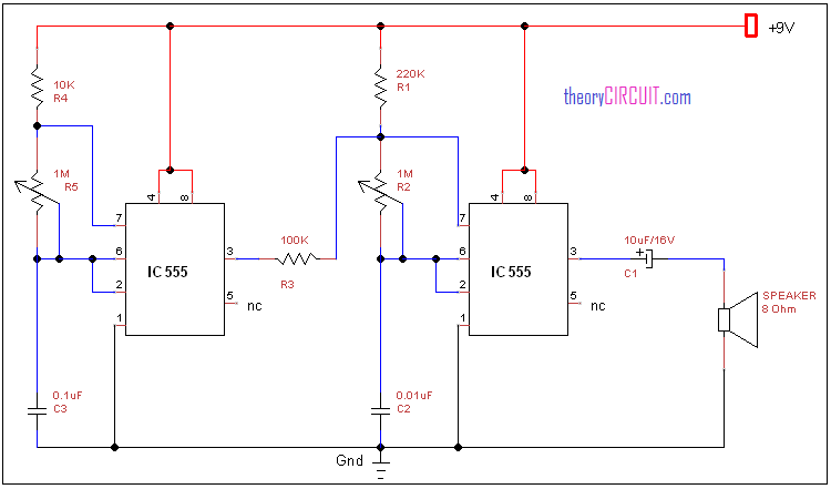
Circuit diagram for electronic horn circuit
Construction and Working
Here first timer IC produce pulse output and second timer IC produce high frequency pulse then the output from the second timer IC fed to the loud speaker. The resistor R4 and R5 reacts as a timing resistors for first timer IC by varying R5 variable resistor we can vary the pulse duration.
Here R2 resistor reacts as a timing resistor for second timer IC by varying R2 we can get different tone horn at output.
You can get IC 555 datasheet here…lm555
Can a 555 dual timer work with the electronic horn circuit
Yes,very Much Provided, All the concerned I/O(Discharge, Contol voltage, Reset,Thresold and Output)Pins are connected accordingly…
Instead 2 NE555 oneNE556.Possible?
Shall we used this circuit for Car Trumpet Horn
Hi Sunilkumar
Just Experiment
We got result in 8 ohm speaker