Last Updated on March 16, 2024
This circuit provides the status about the presence of main power supply through visual and audible output.
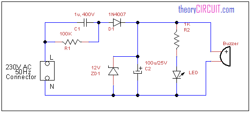
Circuit diagram for main power supply indicator
Construction and Working
Many times we are checking about the presence of power supply through neon indicators on the supply board, when there is no option to know the status of power supply means we use tester or multimeter. Here the simple circuit given to know the presence of main power supply with visual and audible output.
The LED and buzzer in this circuit indicates the main power supply status. 230v AC power supply passed through c1 and R1 components and rectified through D1 diode and then regulated by ZD1 zener diode then the regulated power supply given to the LED and buzzer, through this supply these components gives output by the way we know the status of main power supply.
[stextbox id=”warning”]Take extra care when deal with high ac voltage [/stextbox]
How power supply indicator work?
What is the circuit description of this circuit