Last Updated on March 16, 2024
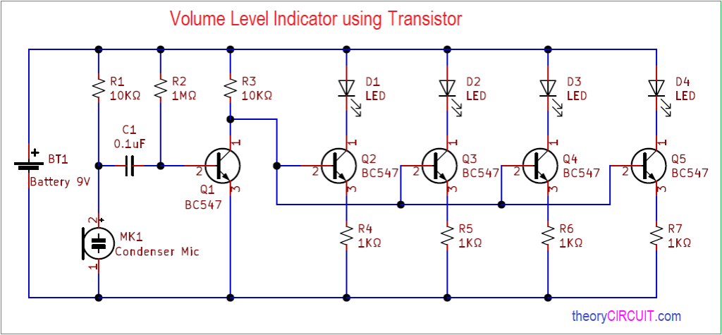
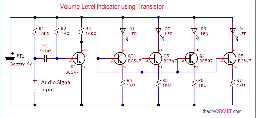
Volume Level Indicator using transistor circuit can be used as a simple VU meter, It can be used to determine sound levels and help us to avoid load sound distortion and noise. This volume level indicator circuit uses a condenser mic to receive the audio or sound and makes the LED glow according to the sound level and power. Another circuit uses direct audio signal and acts as true Volume Unit (VU) meter.
Use different colors of LEDs to easily understand the level, Each stage Transistor acts as switch and barrier to the next stage transistor. We can change the sensitivity level by changing the Resistor values at emitter terminal.
Circuit Diagram
Audio VU meter using Transistor Circuit Diagram
Components Required
- Condenser Mic
- Transistor BC547 = 5
- LED = 4
- Resistor 1KΩ = 4, 10KΩ = 2, 1MΩ = 1
- Capacitor 0.1µ = 1
- Battery 9V
Construction & Working
First Stage in this circuit is sound Receiver by condenser mic and then Q1 transistor Receives audio signal from mic and drives Q2 – Q5 transistors depends on sound level, each LED glows when the connected transistor gets signal. Here each transistor consumes signal and passes to other, hence the highest level signal only reach last transistor Q5. Received signal amplification is done by Q1 transistor hence this transistor drives the other transistor Q2, Q3, Q4, and Q5 transistors depending on the level of sound. This circuit needs calibration before get into application that is Resistor of each transistor needs to be calculated and deployed depends on the required signal indication level.
Transistor BC547
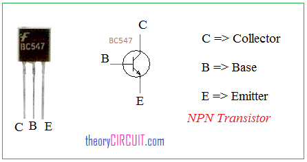
Transistor BC547 is a Active devices termed as a NPN transistor with three terminals, Collector, Base and Emitter, here this transistor drives LED depends on the volume level. Each transistor receives input at base terminal and all emitter terminals are coupled to the ground supply through resistor.


This cannot work? Q2 to Q5 are connected identcally. I think all the LEDs will glow at the same level
This circuit Indicates different volume level through stages of LEDs.
I have the same result…
Is it possible to work if i use headphone out (a phone for ex.) instead of microphone?
I’m not sure what you mean by audio signal exactly. That’s why i ask if headphone out work or not.
Thank you.
yeah you can connect Audio signal from sources instead of microphone.
can you swap the non polar capacitor with the polar capacitor but with the same farad?