Last Updated on October 24, 2024
When you are Implementing two or more Microcontrollers in your project and they need to share and communicate data between them, we have to use communication protocols like Serial Communication, Parallel Communication or Wireless communication. Each one have their own applications and uses. Serial communication is for simple data bit transfer, sharing sensor data or controlling device collaboratively.
Common Serial communication protocols available in typical Microcontrollers are,
- UART (Universal Asynchronous Receiver/Transmitter)
- USART (Universal Synchronous/Asynchronous Receiver/Transmitter)
- I2C (Inter-Integrated Circuit)
- SPI (Serial Peripheral Interface)
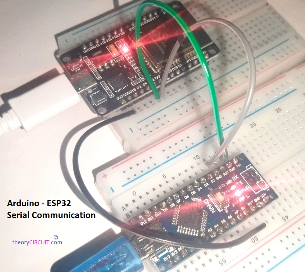
Here we are going to make Arduino and ESP32 Serial Data Communication Setup using simple and easy to use UART method.
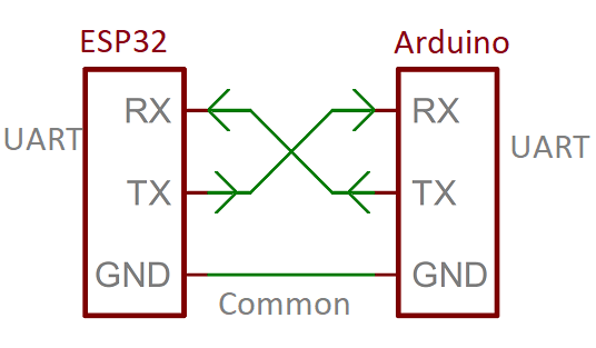
UART Serial Communication
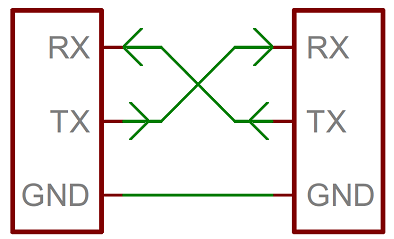
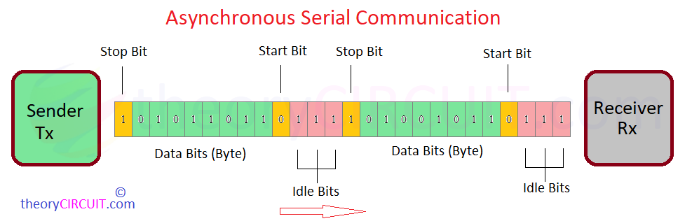
Serial Communication between microcontrollers allows to Transmit (Tx) and Receive (Rx) data in single bit sequence and have start bit in front and stop bit at the end of every eight bit (1 byte) data. Transferring data without any clock base is called as Asynchronous. The Receiver knows the data starting and ending by using the Start, Stop bits and also have some idle bits for spacing between data.
For UART serial communication, Sender (Tx) Microcontroller and Receiver (Rx) Microcontroller must have common speed for data flow which is known as the baud rate. You can program and change the speed (for both) depends on your need but for the basic setup it will be 9600.
UART can Transmit (Tx) and Receive (Rx) at the same time because it uses two independent lines but to avoid data corruption and timing issues UART is used to either send or receive at a given time and vice versa.
Simple UART Setup between Arduino and ESP32
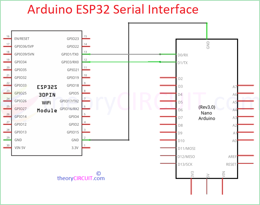
Here Arduino Nano board is used, So it have one UART Channel and fixed pins, Digital Pin 1 for Transmitter (Tx) and Digital pin 0 for Receive (Rx).
But, the DOIT ESP32 Devkit V1 board have three UART channels with the following default pins.
- UART0
- TX: GPIO 1
- RX: GPIO 3
- UART1 (Used for your own communication tasks)
- UART2
- TX: GPIO 17
- RX: GPIO 16
This ESP32 microcontroller based board offers flexible pin assignment. So that you can assign any free GPIO pins to the UART channel and use.
// ESP32 code for multiple UART channels
void setup() {
  // Initialize default serial for debugging (UART0)
  Serial.begin(115200);  // UART0: TX = GPIO 1, RX = GPIO 3

  // Initialize UART1 on custom pins (e.g., TX = GPIO 4, RX = GPIO 5)
  Serial1.begin(9600, SERIAL_8N1, 4, 5);  // UART1 remapped to custom pins

  // Initialize UART2 on default pins (TX = GPIO 17, RX = GPIO 16)
  Serial2.begin(9600, SERIAL_8N1, 17, 16);  // UART2
}
In this code Serial Mentions UART0, Serial1 Mentions UART1 and Serial2 Mentions UART2.
Make the connection as mentioned here,
Arduino Code for Nano to Say Hello Serially!
//Arduino Code
void setup() {
  Serial.begin(9600);
}
void loop() {
  Serial.println("Hello Serial");
  delay(2000);
}
Arduino Code for ESP32 to Receive Serial data
// ESP32 code
void setup() {
Serial.begin(115200); // Initialize Serial Monitor for ESP32
Serial1.begin(9600, SERIAL_8N1, 16, 17); // Initialize Serial1 for communication with Arduino Nano (TX = GPIO 17, RX = GPIO 16)
}
void loop() {
if (Serial1.available() > 0) { // Check if data is available from Arduino Nano
String receivedMessage = Serial1.readStringUntil('\n'); // Read the message from Nano
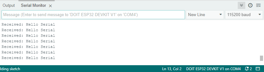
Serial.println("Received: " + receivedMessage); // Print the message to Serial Monitor
}
}
Serial Monitor output from ESP32 (Receiver) Side Arduino IDE.
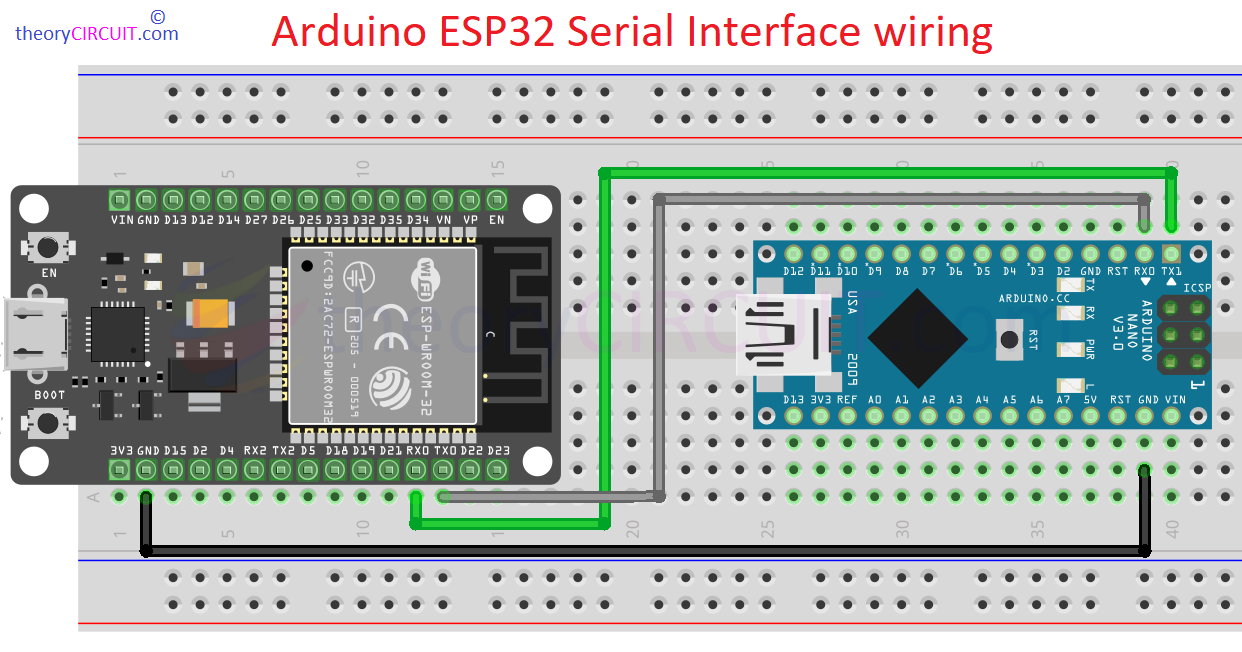
Arduino ESP32 Serial data Interface wiring
Lets look at Arduino and ESP32 Serial Communication Setup for Trimpot Analog Data Transmission.
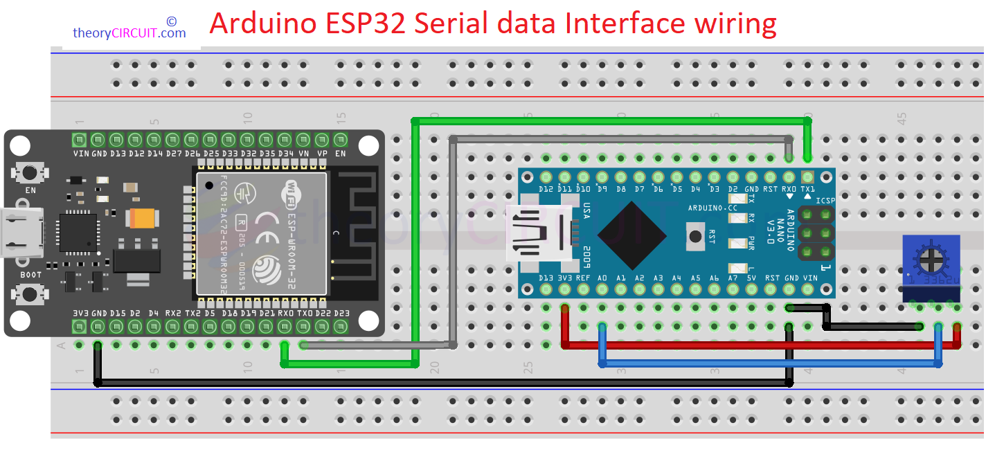
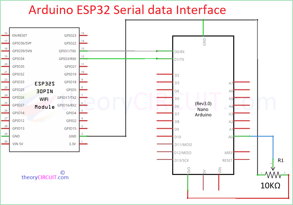
Further, we have connected a Trimpot to the Arduino nano board as a data source, by varying it we can change the input data values to Nano.
Make the following wiring and upload the Code for Arduino Nano and ESP32 individually to receive data serially.
- Connect one terminal of the trimpot to 5V.
- Connect the other terminal to GND.
- Connect the middle pin (wiper) of the trimpot to an analog input pin on the Nano (A0).
- Connect the TX pin of the Nano to the RX pin of the ESP32 (GPIO 16).
- Connect the RX pin of the Nano to the TX pin of the ESP32 (GPIO 17).
- GND of both the Nano and the ESP32 should be connected.
In Schematic we may used TX0 – GPIO1 and RX0 – GPIO3 but in the code we have used different UART channel and Pins. Use Hardware wiring and Code for the exact pins.
Arduino Nano Code
// Arduino Nano code

const int trimpotPin = A0;  // Analog pin where the trimpot is connected
int trimpotValue = 0;       // Variable to store the analog value

void setup() {
  Serial.begin(9600);  // Initialize Serial communication at 9600 baud rate
}

void loop() {
  trimpotValue = analogRead(trimpotPin);  // Read the analog value from the trimpot

  Serial.println(trimpotValue);  // Send the trimpot value to the ESP32
  delay(500);  // Send the value every 500 milliseconds
}
ESP32 Code
// ESP32 code
void setup() {
Serial.begin(115200); // Initialize Serial Monitor for ESP32
Serial1.begin(9600, SERIAL_8N1, 16, 17); // Initialize Serial1 for communication with Arduino Nano (TX = GPIO 17, RX = GPIO 16)
}
void loop() {
if (Serial1.available() > 0) { // Check if data is available from Arduino Nano
String trimpotValue = Serial1.readStringUntil('\n'); // Read the trimpot value from Nano
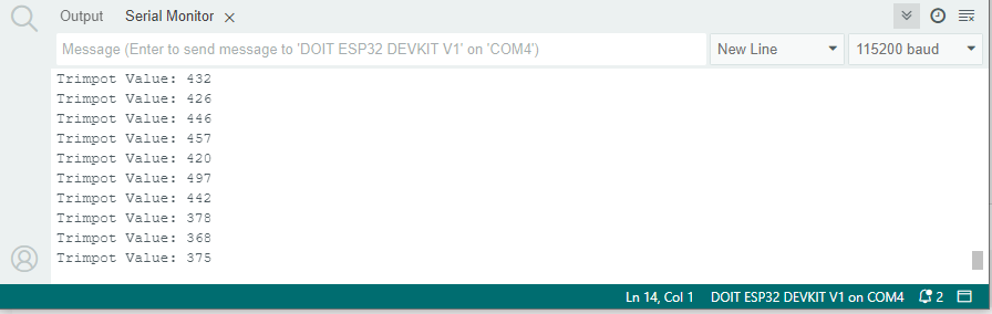
Serial.println("Trimpot Value: " + trimpotValue); // Print the value to Serial Monitor
}
}
Serial Monitor output from ESP32 (Receiver) Side Arduino IDE.
Prototype