
Last Updated on March 16, 2024
We know Nikola Tesla American inventor and electrical engineer Tried an Experiment to Wirelessly transfer Energy from one Place to other, He made Tesla Coil also, So the Wireless Electricity Transfer Technology is far from being a recent innovation. But utilizing it in effective way is happening right now, as we know in Wireless Gadget Charging Circuit, wireless battery charging, electric toothbrushes, RFID tags, induction cooking, and wirelessly charging or continuous wireless power transfer in implantable medical devices like artificial cardiac pacemakers, etc.., Lot of innovations need to be made in this field and its worth. Here is the simple Wireless Power Transmitter and Receiver Circuit Designed with few affordable electronic components.
Both Transmitter and Receiver have Enameled Copper coil winding, A Square wave oscillator and copper coil acts as power transmitter. Copper coil and Bridge Rectifier circuit acts as Receiver. Both are winded 15 turns in 6 CM radius with 20 SWG copper wire.
Circuit Diagram Wireless power Transmitter – Tx
Circuit Diagram Wireless power Receiver – Rx
Components Required for Tx PCB (BOM)
| 1 | C1 | 0.1µF | C_Disc_D3.0mm_W2.0mm_P2.50mm | 1 | ||
| 2 | C2 | 50µF | CP_Radial_D5.0mm_P2.50mm | 1 | ||
| 3 | R1 | 30KΩ | R_Axial_DIN0207_L6.3mm_D2.5mm_P10.16mm_Horizontal | 1 | ||
| 4 | R2 | 10KΩ | R_Axial_DIN0207_L6.3mm_D2.5mm_P10.16mm_Horizontal | 1 | ||
| 5 | R3 | 1KΩ | R_Axial_DIN0207_L6.3mm_D2.5mm_P10.16mm_Horizontal | 1 | ||
| 6 | L1 | 20 Turns Coil | TerminalBlock_bornier-2_P5.08mm | 1 | ||
| 7 | U1 | LM386 | DIP-8_W7.62mm_LongPads | 1 | ||
| 8 | J1 | 5V to 12V | TerminalBlock_Altech_AK300-2_P5.00mm | 1 |
Components Required for Rx PCB (BOM)
| 1 | C1 | 0.01μF | C_Disc_D3.0mm_W2.0mm_P2.50mm | 1 | ||
| 2 | C2 | 100μF | C_Radial_D5.0mm_H11.0mm_P2.00mm | 1 | ||
| 3 | C3 | 1μF | C_Radial_D4.0mm_H5.0mm_P1.50mm | 1 | ||
| 4 | L1 | L | TerminalBlock_bornier-2_P5.08mm | 1 | ||
| 5 | D2 | D_Bridge_+A-A | Diode_Bridge_Round_D9.0mm | 1 | ||
| 6 | U1 | L7805 | SIP3_11.6×8.5mm | 1 | ||
| 7 | J1 | Screw_Terminal_01x02 | TerminalBlock_bornier-2_P5.08mm | 1 |
Construction & Working
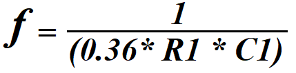
IC LM386 Configured as Square wave oscillator, Timing Resistor R1 and Timing Capacitor C1 decides the output frequency range.
When the power supply (5V to 12V) applied to the Power transmitter circuit then the LM386 Starts to oscillate 1 KHz Square pulse signal and that is carried to the Coil. Hence the Coil magnetic field start to oscillate in 1 KHz. It produce strong fluctuating magnetic field.
In other end Receiver circuit Coil is connected with Bridge rectifier and positive voltage regulator 7805. When Receiver coil place near to the transmitter coil, electro magnetic flux will induce emf (electromotive force) in receiver coil, amplitude of induced emf is depends on the number of winding and distance between magnetic source that is transmitter coil. Potential difference produced in the receiver coil rectified by bridge rectifier and regulated by positive voltage regulator. Make transmitter and receiver coil depends on you need.
Printed Circuit Board
Wireless power Transmitter – Tx PCB Gerber Files.
Interactive Board Viewer For Wireless Power Transmitter PCB


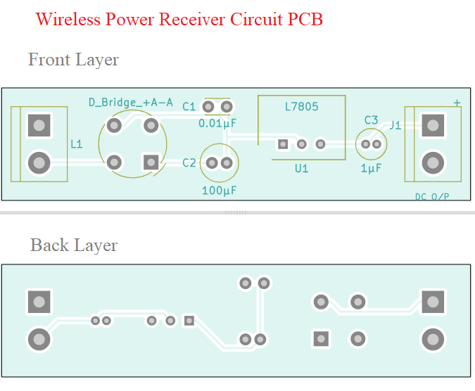
Wireless power Receiver – Rx Gerber Files.
Hello,
I am interested in building a compact wireless receiver device that fits into the size of a business card dimensions or close to it. Can you share your thoughts on how to go about doing this? what would be the best practices to keep in mind as I build out the pcb layout? secondly what is the least z height setup I can expect to have to make this work? Lastly are there companies who can assist on this project?
Many thanks for your help.