Last Updated on March 16, 2024
By using Triac, Diac and variable resister elements we can create effort less ceiling fan regulator and this regulator circuit regulates ceiling fan speed smoothly.
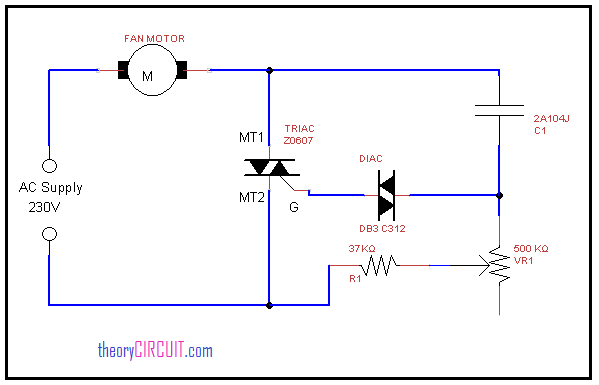
Ceiling Fan regulator connection diagram
Construction and Working
The power supply phase line is connected with one terminal of fan and other terminal from fan is connected with regulator circuit, here TRIAC connected across the fan and neutral power line, the gate terminal is connected with DIAC, the capacitor 2A104J is an polymer capacitor which is connected with variable resistor, these components are controls the voltage flow through the fan.
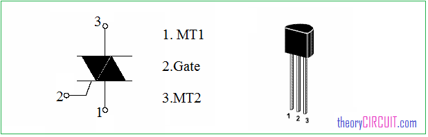
TRIAC Z0607
The Z0607 is three terminal plastic enclosed TRIAc element, this is suitable for fan speed control and light control. It has low gate triggering current hence it can be directly controlled by micro controller output.
Symbol and pinout of TRIAC Z0607
The variable resistor placed in this circuit is VR1 500KΩ, Connect variable resistor to increase resistance in clock wise rotation then only you can get high speed fan rotation when you rise the variable resistor.
“Take Extra care and safety measures to handle high AC supply”
Datasheet
You can get datasheet of TRIAC Z0607 here.
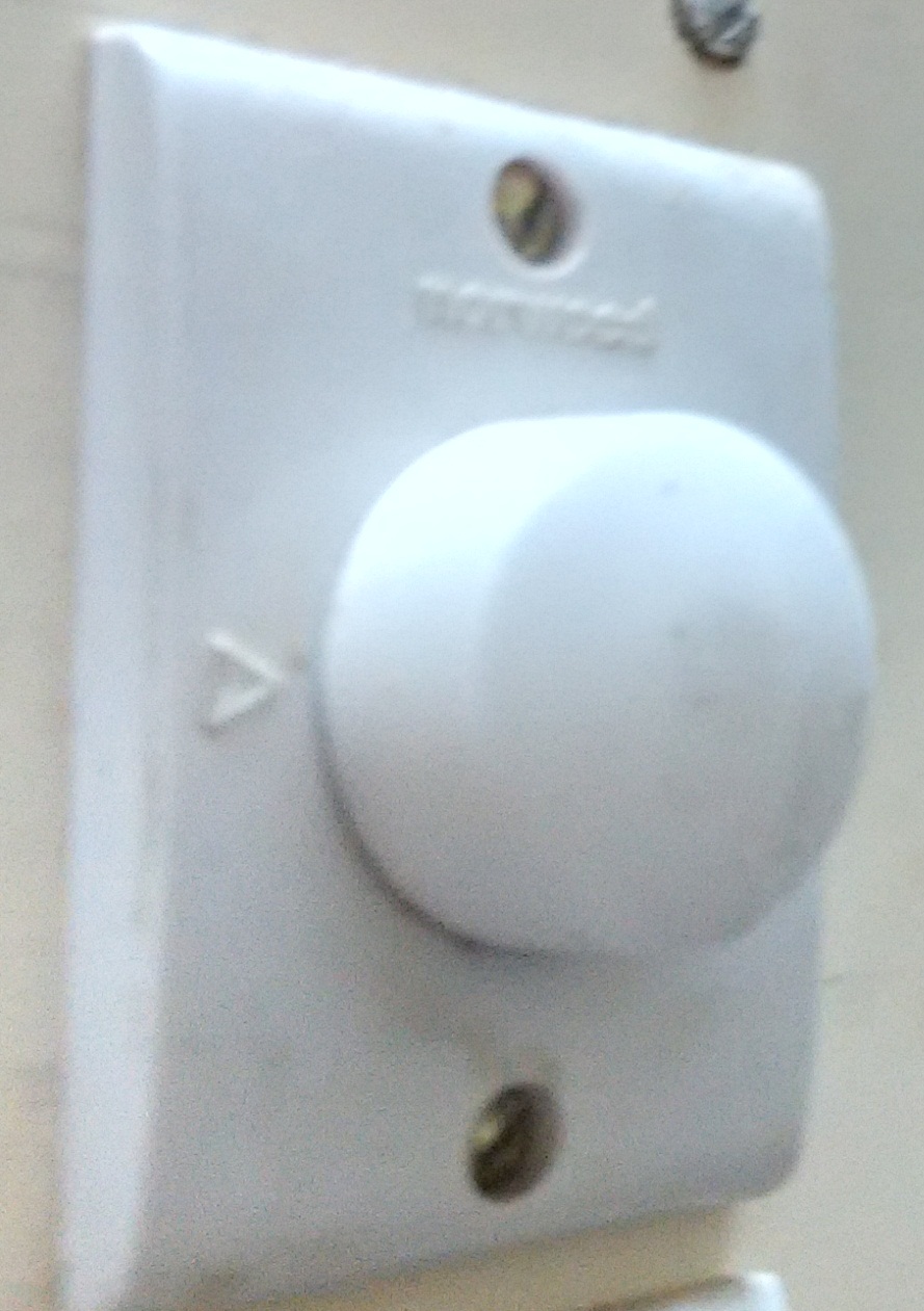
Prototype

I want to control the speed of the fan without using a knob . By applying pwm pulses directly to the triac but . I don’t have idea on how to do it . I am using LabVIEW software.
Take Extra care and safety measures to handle high AC supply
Thanks for the useful info in this article, It means a lot.
Such an insightful information, Explanation is very clear, Thank you.