
Last Updated on October 31, 2024
To save electricity and reduce man power we can simply convert normal street light into Automatic by using Automatic Street light controller using LDR. We know LDR (Light Dependent Resistor) has been used in many applications and by proper employing in circuit LDR can acts as a perfect light sensing element. This circuit will Turn ON the street light when sunlight goes below the visibility, and automatically turn OFF the street light when the sunlight comes.
This automatic street light is operates based on the atmosphere sun light, when the sun set occurs this circuit detects darkness and makes street light ON and when the sun rises this circuit detects and makes the street light OFF automatically.
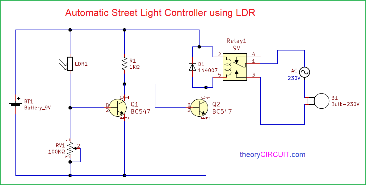
Circuit Diagram
Components Required
- LDR 5mm
- Transistor BC547 (NPN) = 2
- Relay 9V (SPDT)
- Diode 1N4007
- Variable Resistor 100KΩ
- Resistor 1KΩ
- Battery 9V
- 230V electric Bulb
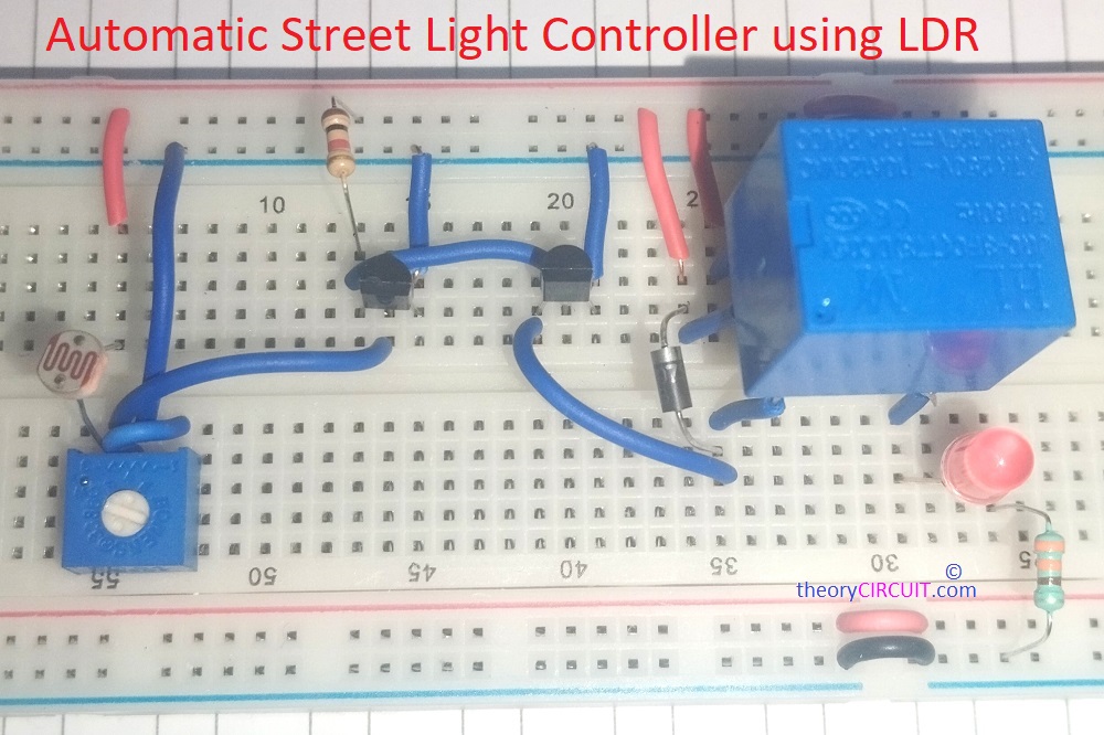
Working Video
Here LED is connected with relay for showing, how this circuit works!
Construction & Working
This automatic street light controller circuit using ldr involves in handling of High Voltage AC supply, Handle with Extreme Care.
LDR or Photoresistor is the sensor here and the Variation in the Resistance Converted into Relay switch Turn ON and OFF position through two transistors. LDR is connected between bias lines through Variable Resistor RV1 and we can change the sensitivity level of LDR by changing Variable Resistor value. Transistor Q1 base is connected in connecting joint of LDR and Variable Resistor. Output of Q1 transistor is connected to the Q2 transistor base.
A 9V Relay is connected at the collector terminal of Q2, here Q2 transistor acts as a Switch to make Relay coil turn on and off by connecting to bias. Diode D1 protects relay coil from back emf. At the Relay Normally open (N/O) terminal 230V bulb terminal is connected and another terminal of bulb is connected to the AC supply (neutral) and AC supply phase is connected to the Relay Common terminal. When the Relay coil gets energized then N/O terminal makes contact with common terminal and bulb starts to glow.
When the sun light falls on LDR it becomes less resistive element and allows bias to appear at Q1 base then Q1 becomes turn ON and so there is no bias at Q2 base hence the Q2 stands in turn OFF condition so the Relay coil don’t get supply and stays in off condition. When there is no light falls on LDR it becomes High resistive element and there is no bias appears at Q1 base, hence Q1 becomes turn OFF and bias through R1 appears at Q2 base and it becomes turn ON hence the Relay coil gets supply and becomes energized and Makes the (N/O) contact as closed to to common contact then bulb starts to glow.