
Last Updated on September 25, 2025
Simple Automatic Street Light Circuit Using IC 741 is easy to construct with few easily available components. In this circuit LDR (light depended Resistor) is used as a light-dark Sensor. Operational amplifier IC 741 drives Relay through BC547 Transistor as inverting amplifier.
You can connect any Light Source to the Relay. (How to use Relay?). We know IC 741 is a general purpose operational Amplifier, Here 8 Pin dual in line package operational amplifier used and configured as inverting amplifier.
Circuit Diagram

Components Required
- Operational Amplifier IC 741
- 12V SPDT Relay
- LDR
- Transistor BC557 PNP
- Diode 1N4001
- Variable Resistor 10KΩ
- Resistor 1KΩ
- Resistor 10KΩ
- Resistor 270Ω = 2 (optional for balancing voltage divider)
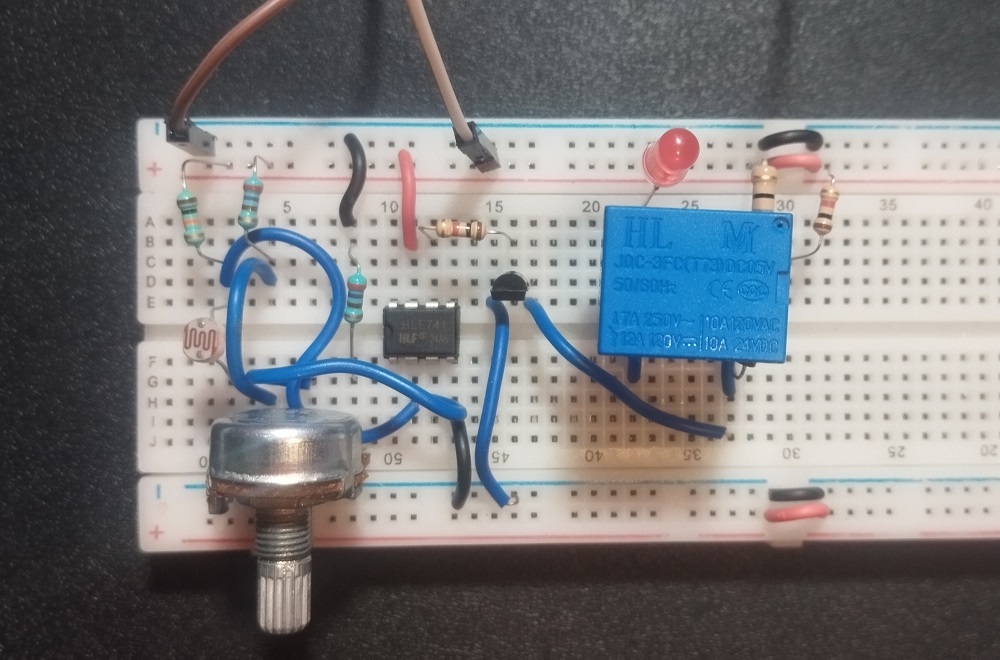
Prototype on Breadboard
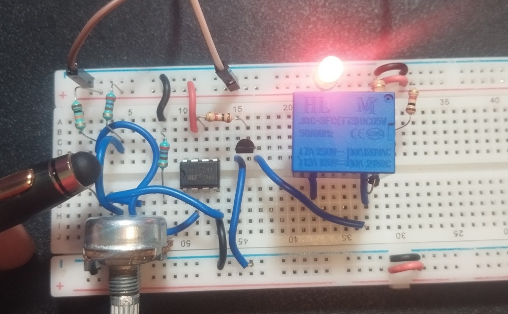
Automatic Street Light Circuit Using IC 741 In Action
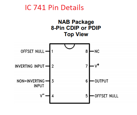
IC 741 Pin Details
Construction & Working
Purpose of this Automatic Street Light circuit is to turn ON light bulb during night time and turn OFF during day time. Hence we used LDR as a light/dark sensing device (Place the sensor above or behind light source, that is LDR should sense natural light only).
Output terminal from operational amplifier is connected with base terminal of transistor BC557, 12 volt SPDT Relay coil is connected between +12V and transistor Q1 Emitter terminal. Variable Resistor RV1 gives the Sensitivity level to Non Inverting input of IC 741.
When there is natural light then the LDR Resistance level goes down so that voltage and current flow through R1 easily goes to the ground or negative. Hence the inverting input receives low range voltage and current due to that Output voltage decrease and turns OFF the transistor. So the Relay coil gets disconnected from bias and turns OFF the light source connected with the common and N/O pins.
LDR Resistance level increase due to darkness after sunset. Hence the maximum voltage and current flow through R1 Reaches inverting input of Op-Amp, So the output voltage also gets increase and turns ON the transistor Q1 by the way Relay coil gets bias and turns ON the light Source connected with the common and N/O pins.