
Last Updated on March 16, 2024
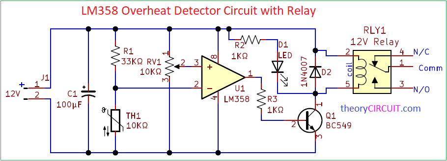
Simple LM358 Overheat Detector Circuit with Relay is Designed to act as a Stand alone Overheat or Temperature Limit Switch. This circuit uses a NTC Thermistor as a Temperature Sensor and Operational Amplifier IC LM358 as a Comparator and a 12V SPDT Relay.
By using this Temperature Switch circuit we can control target load depends on some threshold temperature, this temperature level can be adjusted and Calibrated by using Variable Resistor RV1.
Circuit Diagram
Components Required (BOM)
| 1 | C1 | 100µF | C_Radial_D4.0mm_H5.0mm_P1.50mm | 1 | ||
| 2 | R2, R3 | 1KΩ | R_Axial_DIN0204_L3.6mm_D1.6mm_P7.62mm_Horizontal | 2 | ||
| 3 | R1 | 33KΩ | R_Axial_DIN0204_L3.6mm_D1.6mm_P7.62mm_Horizontal | 1 | ||
| 4 | D2 | 1N4007 | D_DO-41_SOD81_P10.16mm_Horizontal | 1 | ||
| 5 | D1 | LED | LED_D5.0mm_Clear | 1 | ||
| 6 | U1 | LM358 | DIP-8_W7.62mm | 1 | ||
| 7 | RV1 | 10KΩ | Potentiometer_Bourns_3266W_Vertical | 1 | ||
| 8 | TH1 | 10KΩ | R_Axial_DIN0204_L3.6mm_D1.6mm_P1.90mm_Vertical | 1 | ||
| 9 | RLY1 | 12V Relay | Relay_SPDT_SANYOU_SRD_Series_Form_C | 1 | ||
| 10 | Q1 | BC549 | TO-92_Inline | 1 | ||
| 11 | J1 | 12V | PinHeader_1x02_P2.00mm_Vertical | 1 |
Construction & Working
This Temperature Sensor switch circuit contains a temperature sensor (NTC Thermistor), a Comparator amplifier and a 12 Volt SPDT Relay.
What is Thermistor?
Thermal Sense Resistor or Temperature Depended Resistor is known as a Thermistor. This device Resistance changes according to the temperature. Thermistor can be a NTC or PTC which means,
NTC – Negative Temperature Coefficient.
PTC – Positive Temperature Coefficient.
Here NTC – Element Resistance Decrease when Temperature Increases. PTC – Element Resistance Increase when Temperature Increases.
In this Overheat detector circuit 10KΩ Range NTC Thermistor is connected with Inverting Input of LM358. Non Inverting input of LM358 is connected to the variable terminal of RV1. So the operational amplifier detects signal from RV1 and thermistor then compares and gives output at pin 1. This output signal is not enough to drive a 12V Relay coil hence Transistor Q1 BC549 used as a switch for Relay coil. Here LED indicates the status of ON condition of Relay.
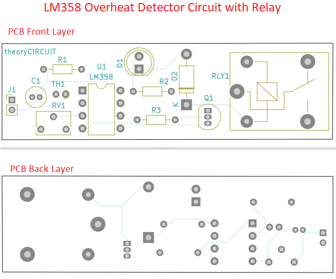
Printed Circuit Board
LM358 Overheat Detector Circuit PCB Gerber Files.
Interactive Board Viewer


Says either use PTC or NTC. It appears to me if the PTC is used, you would likely want to connect the PTC to the inverting input, pin 3 along with the 33k and the Pot to the inverting pin, #3 for the circuit to operate so as to turn off when hot. The way the text and diagram are here, with the NTC 10k thermistor when the temp goes up and R goes down the op amp switches the output off. The LED goes out and the relay opens. If the circuit is not modified this way then it would effectively be a cool temp turn off instead of a high temp turn off. The relay could be used to power a fan on or off.
What problems you have faced after implementing this project
Bonjour,
Je viens d’essayer ce circuit. J’ai attaché deux potentiomètres de 20k aux deux entrées non inversseuses du lm358 et fonctionne. Une led à la sortie 1 et une autre à la sortie 7. J’ai aussi attaché en série le NTC avec une résistance de 4.7k.
Mais j’ai remarquer lorsque j’applique la chaleur au NTC, La sortie 1 s’éteint et la sortie 7 s’allume. C’est ce que je souhaitais voir. Toute fois, il y u petit moment de une à deux secondes qui s’écoule avant que la led de la sortie de 7 puisse s’allumer. Je ne sais pas comment interpréter cela ni comment rendre réduire cet hysteresis. Voudriez vous m’aider à savoir comment rendre l’allumage de la led de pin 7 automatique? Il en est de même pour l’extension de cette led pour voir la led de la pin 1 s’allumer. Il y a toujours cette petite durée là qui s’écoule.
Merci
Translation
(Good morning,
I just tried this circuit. I attached two 20k potentiometers to the two non-inverting inputs of the lm358 and it works. One LED at output 1 and another at output 7. I also connected the NTC in series with a 4.7k resistor.
But I noticed when I apply heat to the NTC, Output 1 turns off and Output 7 turns on. This is what I wanted to see. However, there is a short time of one to two seconds which passes before the LED of output 7 can light up. I don’t know how to interpret this or how to reduce this hysteresis. Would you like to help me know how to make the pin 7 LED turn on automatically? The same goes for extending this LED to see the pin 1 LED light up. There is always this little time that passes.
THANKS)