
Last Updated on March 29, 2024
You may witnessed smooth Camera Gimbals, 3D Printers, Drones and CNC Machines.., and wonder how precisely they moving and lifting, reason behind these are Servo Motors.
What is the Servo Motor?
A Servo Motor is a type of electric motor specially designed for precise and accurate rotation and movement. We can call it as Smart motor because it contains Sensor and control circuit with feedback to inform the current position of shaft. Hence it always moves and rotates precisely. Servo Mechanism consist of multiple gears and it makes this servo motors to operate with High torque to inertia ratio, that is the turning and lifting force are much greater that their size. That is why these servo motors are used in Robotics, Industrial applications etc.,
There are different types and custom servo motors are available, based on the usage we can list three,
- AC Servo Motor
- DC Servo Motor
- Micro servo Motor
For experimenting and making electronic stuff, we use DC Servo Motor or Micro Servo Motor both are works with DC power supply and control circuit, mostly servo motor use PWM (Pulse Width Modulation) signal as control signal. When you look for servo motor in the internet, it termed as Kg/cm that is Kilogram per centimeter, which is the standard term to rate the servo motors. Most experimental servo motors are rated from 1.2 Kg/cm, 4 Kg/cm, 15 Kg/cm .., For hobby projects SG90 micro servo motors are mostly used (You may noticed in Arduino Servo motor Interface guides). These servo motors are lift their noted weight from 1 Cm, if the load weight distance more than 1 Cm then lifting power of servo motor will decrease.
Servo Mechanism
For Controlled precise movement of motor shaft servo Mechanism plays important role. A closed loop with feedback and control circuit inside servo motor is called as servo mechanism.
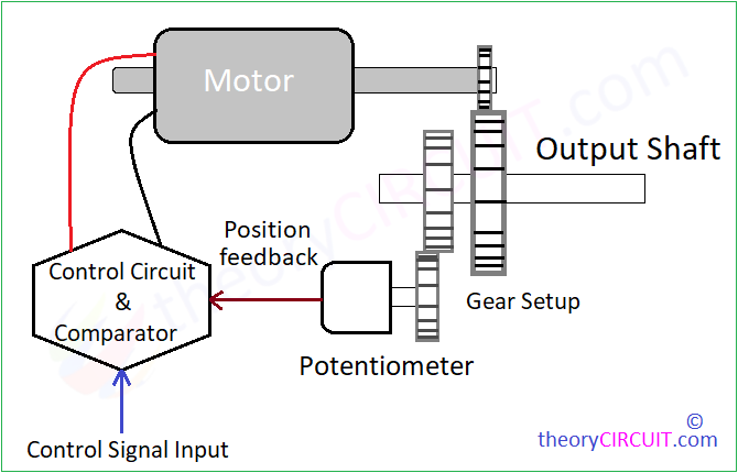
A control circuit & Comparator with control input signal and position feedback will give required bias to the motor. Depends on the received bias, motor shaft will turn (rotate), attached gears also makes rotation, A 360 degree potentiometer attached with gears also rotates and changes its Resistance value, this changes in resistance taken as position feedback and comparator circuit compares it with control signal and allow or limit bias to motor and this operation repeats.
How Servo Motor Works?
As previously said Motor insider Sevo Mechanism will receive required bias through Control Circuit, and starts rotate shaft when it receive bias, Gears attached with shaft will increase torque, it causes decrease in RPM, so that saft rotation movement is controlled. Potentiometer shaft attached with gears also moves when motor shaft rotates, and the supply through potentiometer (feedback signal) and control signal (PWM) being compared by comparator and the difference signal is applied to the control circuit, here it allows required level of DC to the motor in PWM format and makes precise rotation.
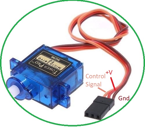
Micro Servo Motor mostly work with 5V DC supply, and it requires +V, Gnd and PWM signal for its operation, Servo motors are very easy to interface and control by using Controlled PWM signal circuit or Microcontrollers and development boards Arduino, Raspbery pi, ESP32 etc.,
Servo motor degree of rotation is based on the ON time (HIGH) in the PWM signal, so we can either program or use sensor to make PWM signal with required ON time and make proper rotation movement in Servo motor shaft.
As you see with respect to PWM signal (HIGH), servo motor shaft rotates with precise angle, by coding and using sensor we can drive many possible applications. Some examples from theorycircuit.com
1. Simple Automatic Arduino Pet Feeder
2. Analog Input to servo motor using Arduino