
Last Updated on March 29, 2024
Voltage Divider Circuits are very important in Analog Electronics as well as Sensor interfacing to the microcontrollers. Basic operation of this simple circuit is to reduce the input Voltage level (Vin) into desired Low Voltage Output (Vout) by using two passive Resistors. By understanding its operation and needs we can bias any components with the given input voltage.
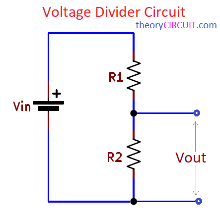
Basic voltage divider circuit is constructed by using two resistors (R1 and R2) as illustrated in the circuit diagram. You have to Calculate the Resistor Values for R1, R2 and Vin to get the desired output voltage across the Resistor R2. Use Voltage Divider Circuit Calculator or use the Following formula to calculate the Vout Value.
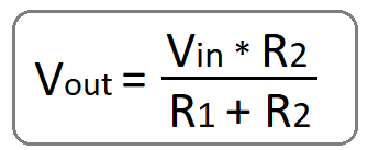
Output Voltage Formula for two Resistor Voltage Divider Network.
- Vin = Input Voltage to the Divider circuit
- Vout = Output Voltage taken between Junction of two Resistors and Gnd. (Voltage Across R2)
- R1 = Top Resistor
- R2 = Bottom Resistor
Circuit Diagram
Basic Two Resistor Voltage Divider Circuit
Two Same Value Resistors in Voltage Divider circuit
Components List
- Resistors (same value and different Value)
- Variable Resistor
- LDR (Light Dependent Resistor)
- Bread Board
- Multimeter
- Power supply (Vin)
Construction & Working
Operation of this Voltage Divider circuit is depends on the distribution of voltage across the Resistor R1 and R2. As per the Ohm’s law (V=I*R), Current flowing through series Resistors are same and the Voltage drop across each Resistor is proportional to its Resistance value. Hence the Vout is always lesser than the Vin.
Voltage Divider Examples
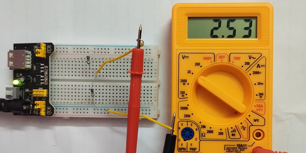
When you are using two same value Resistors (1KΩ), and Vin is 5V then the output voltage Vout is.
Vout = Vin * (R2 / (R1 + R2))
Vout = 5 * (1000 / (1000 +1000))
Vout = 5 * (1000 / (2000))
Vout = 2.5V
Two 1KΩ Resistors in Voltage Divider
When you are using two different value Resistors (R1 = 1KΩ, R2 = 2.2KΩ), and Vin is 5V then the output voltage Vout is.
Vout = Vin * (R2 / (R1 + R2))
Vout = 5 * (2200 / (1000 +2200))
Vout = 5 * (2200 / (3200))
Vout = 3.43V
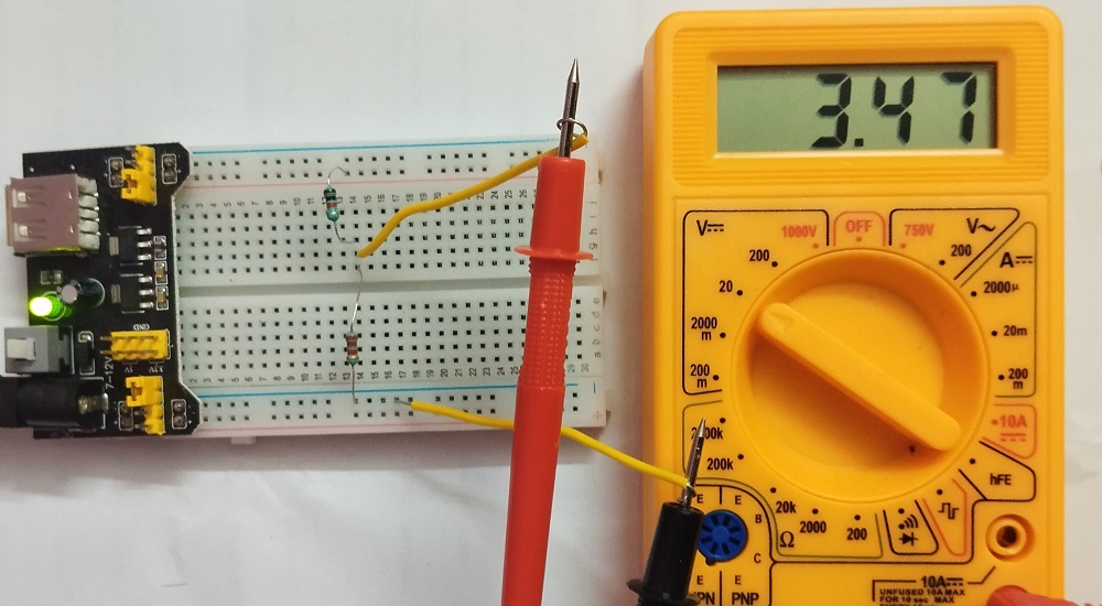
R1 = 1KΩ, R2 = 2.2KΩ in Voltage Divider
Notes:-
- Any Same Value Resistors (R1 and R2), will give half the value of Vin at the output (Vout).
- Very Low Value of R2 than R1 will give nearly 0 Vout.
- Very low Value of R1 than R2 will give nearly Vin voltage as Vout.
Applications of Voltage Divider circuit
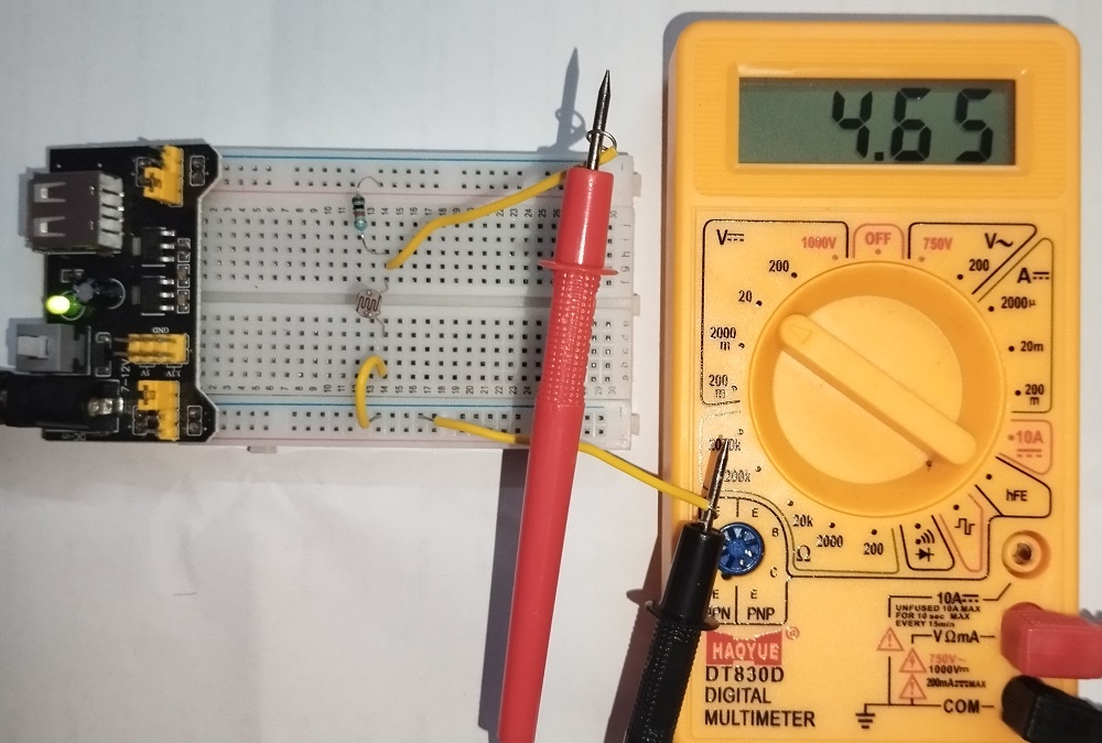
Most Analog passive sensors will need a bias through Voltage divider setup, here the LDR (Light Dependent Resistor) and Resistor acts as Voltage divider and the output voltage is depends the concentration of light falls on the surface of LDR. Because the Resistance value of LDR decrease depends on the light intensity.
In Volume Control and other Variable Resistor applications. Voltage divider concept is applied.
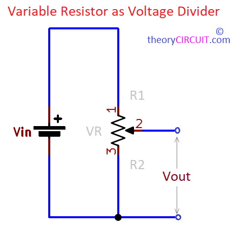
As the Variable Resistor have Three terminal, the Variable out terminal acts as node point to the Resistive track beyond and after. It creates a junction and makes R1 and R2 division in the potentiometer or variable resistor and gives Vout from Vin.
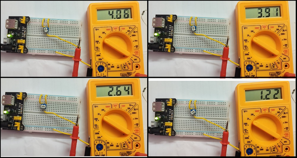
For this variable resistor 5V is applied as Vin and Vout taken at different ranges of resistance. Some more applications.
- Voltage Level Shifting
- Biasing
- Power supply division
- Sensor interfacing
- Signal Conditioning