
Last Updated on March 16, 2024
Monitoring the Current flow in a device by a mains powered appliance is just complicated one. Because continuous current flow monitoring by a circuit creates current isolation in target device, so we need to measure current flow without affecting the target device. Hall effect current sensor circuit Using Arduino helps to monitor and log current flow to a device.
We measure current flow in a circuit to calculate several specifications, for an electronic designer it is important to measure and data logging the current level with respect to time, some times multi-meter with current measurement felicity helps us to measure the same. Do you look for mains current sensor circuit with data logging, then this article helps you in better way.
The popular and easy method to current sensing is Hall effect current sensing method.
What is Hall Effect?
When a current carrying conductor was placed in a magnetic field, a voltage proportional to the field was generated. This is known as hall effect.
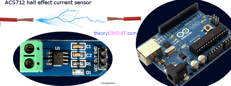
ACS712 Hall Effect Current Sensor
 The ACS712 from Allegro, provides precise solutions for AC or DC current sensing which is suitable in industrial, commercial, and communications systems. The device package allows for easy implementation by the customer. Typical applications include motor control, load detection and management, switch mode power supplies, and overcurrent fault protection. The device is not intended for automotive applications. The device consists of a precise, low-offset, linear Hall circuit with a copper conduction path located near the surface of the die.
Applied current flowing through this copper conduction path generates a magnetic field which the Hall IC converts into a proportional voltage. Device accuracy is optimized through the close proximity of the magnetic signal to the Hall transducer. A precise, proportional voltage is provided by the low-offset, chopper-stabilized BiCMOS Hall IC, which is programmed for accuracy (acs712-datasheet).
Features
▪ Low-noise analog signal path
▪ Device bandwidth is set via the new FILTER pin
▪ 5 μs output rise time in response to step input current
▪ 80 kHz bandwidth
▪ Total output error 1.5% at TA = 25°C
▪ Small footprint, low-profile SOIC8 package
▪ 1.2 mΩ internal conductor resistance
▪ 2.1 kVRMS minimum isolation voltage from pins 1-4 to pins 5-8
▪ 5.0 V, single supply operation
▪ 66 to 185 mV/A output sensitivity
▪ Output voltage proportional to AC or DC currents.
ACS 712 Block Diagram
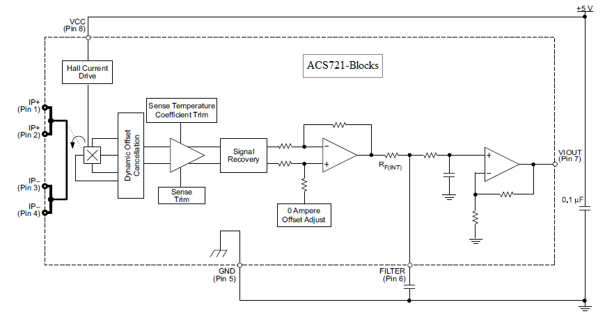
How it Works?
Here the ACS712 current sensor ic placed in a breakout board and connect with Current sense target load and Micro-controller. The sensor detects current flow through IP+ and IP- pins (Resistance Current Conductor), it creates hall effect and then proportional voltage output taken form pin 7 (VIOUT) of ACS712. It can be directly fed into micro controllers Analog input pin after the filter arrangements.
Differential Current Amplifier
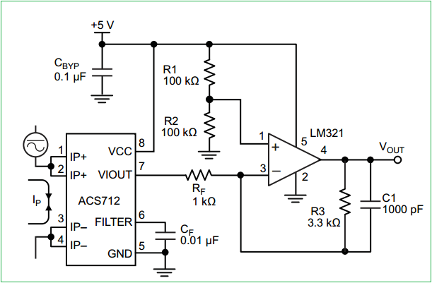
This configuration increases gain to 610 mV/A. For an oscillating current output this differential amplifier circuit helps to bring steady state Vout. This is an typical application circuit from datasheet.
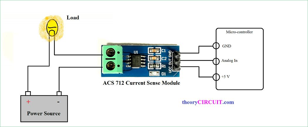
Interfacing Arduino and ACS712-Hookup

As per the breakout application note hall effect current sensor connected with target load and output signal is connected with well known Arduino’s A0 (Analog input pin 0). This sensor breakout consumes power from Arduino power source (+5 and GND). After the setup is over upload the following arduino code to measure the current flow to the load.
DC Current Measuring Arduino Code
void setup() {

  Serial.begin(9600);
}

void loop() {

  float average = 0;
  for(int i = 0; i < 1000; i++) {
    average = average + (.0264 * analogRead(A0) -13.51) / 1000;

  //5A mode, if 20A or 30A mode, need to modify this formula to
    //(.19 * analogRead(A0) -25) for 20A mode and
    //(.044 * analogRead(A0) -3.78) for 30A mode

    delay(1);
  }
  Serial.println(average);
}
AC Current Measuring Arduino Code
#define CURRENT_SENSOR A0  // Define Analog input pin that sensor is attached

float amplitude_current;      // Float amplitude current
float effective_value;       // Float effective current

void setup()
{
    Serial.begin(9600);
    pins_init();
}
void loop()
{
    int sensor_max;
    sensor_max = getMaxValue();
    Serial.print("sensor_max = ");
    Serial.println(sensor_max);

    //the VCC on the Arduino interface of the sensor is 5v

    amplitude_current=(float)(sensor_max-512)/1024*5/185*1000000; // for 5A mode,you need to modify this with 20 A and 30A mode;
    effective_value=amplitude_current/1.414;

    //for minimum current=1/1024*5/185*1000000/1.414=18.7(mA)
    //Only sinusoidal alternating current

    Serial.println("The amplitude of the current is(in mA)");
    Serial.println(amplitude_current,1);

    //Only one number after the decimal point

    Serial.println("The effective value of the current is(in mA)");
    Serial.println(effective_value,1);
}
void pins_init()
{
    pinMode(CURRENT_SENSOR, INPUT);
}
/*Function: Sample for 1000ms and get the maximum value from the S pin*/

int getMaxValue()
{
    int sensorValue;    //value read from the sensor
    int sensorMax = 0;
    uint32_t start_time = millis();
    while((millis()-start_time) < 1000) //sample for 1000ms
    {
        sensorValue = analogRead(CURRENT_SENSOR);
        if (sensorValue > sensorMax)
        {
            /*record the maximum sensor value*/

            sensorMax = sensorValue;
        }
    }
    return sensorMax;
}
[stextbox id=”warning”]Warning: Several milliamps enough to hurt humans, Take much care while you measure current. [/stextbox]
how to modify code for 20a mode
Replace (.0264 * analogRead(A0) -13.51) with (.19 * analogRead(A0) -25).
I used this program to read current with arduino but it’s not working …..Can you help with this regarding…..Thankyou
Dear Sir /Mam,
How to find out Min & Max current to be measure with ACS 712 along with A mega 2560 MC…can any one help me….Thank you
Can we use it to measure VFD output current