
Last Updated on March 16, 2024
Simple Inductive Proximity Switch Circuit designed by using IC TCA505BG from Siemens. TCA505BG is a IC for Inductive Proximity switch with short circuit production. It has wide Supply Voltage Range from 4V to 40V. It consumes low current less than 0.8mA. This IC has short circuit and overload protection of output stages and external components.
What is Proximity Switch?
Proximity can be defined as Closeness, Here proximity switch is a device or sensor detecting the proximity that is closeness of some object.
This Inductive Proximity switch circuit detects near by objects which have magnetic characteristics like metal objects.
Circuit Diagram
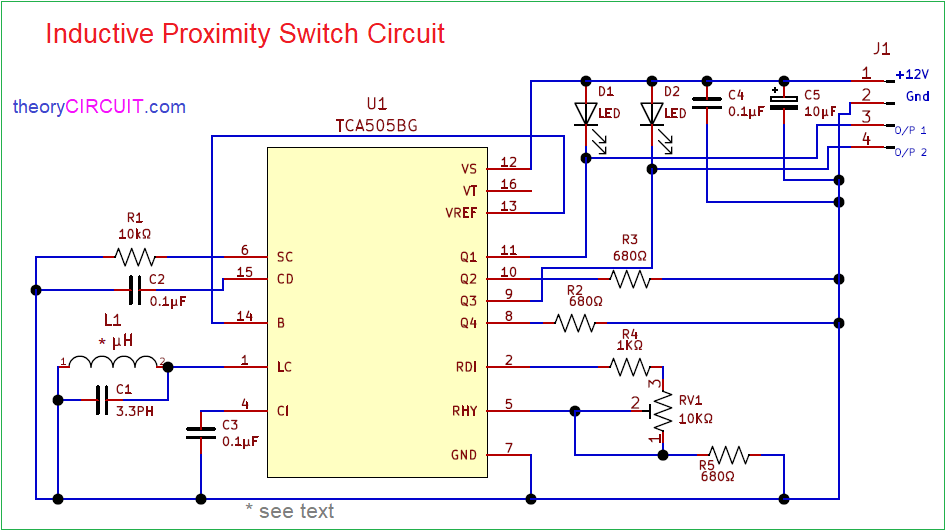
Components Required (BOM)
| 1 | C2, C3, C4 | 0.1µF | C_0805_2012Metric | 3 | ||
| 2 | C1 | 3.3PH | C_0805_2012Metric | 1 | ||
| 3 | C5 | 10µF | C_0805_2012Metric | 1 | ||
| 4 | R2, R3, R5 | 680Ω | R_0805_2012Metric | 3 | ||
| 5 | R1 | 10kΩ | R_0805_2012Metric | 1 | ||
| 6 | R4 | 1KΩ | R_0805_2012Metric | 1 | ||
| 7 | L1 | 680µH | L_Axial_L5.3mm_D2.2mm_P7.62mm_Horizontal_Vishay_IM-1 | 1 | ||
| 8 | D1, D2 | LED | LED_0805_2012Metric | 2 | ||
| 9 | U1 | TCA505BG | SOIC127P600X175-16N | 1 | ||
| 10 | RV1 | 10KΩ | Potentiometer_Bourns_3296W_Vertical | 1 | ||
| 11 | J1 | Conn_01x04_Male | PinHeader_1x04_P2.00mm_Vertical | 1 |
Construction & Working
Main part of this proximity Switch circuit is Sensing Inductor L1, Use Inductor wire wound range from 490µH to 720µH as a Sensing Inductor L1, test with the prototype before fixing the L1 Value.
This Circuit designed to operate with 12V DC supply. Depends on Inductor L1 Value and tank circuit L1, C1 inductive proximity sensing range will vary on an average 3mm – 15mm. In this circuit D1 LED indicates the detection of metal or proximity. D2 LED indicates the no detection of metal or proximity.
| Inductive Proximity | D1 LED | D2 LED |
| No Metal Detection | OFF | ON |
| Metal Detection | ON | OFF |
We can use this signal to drive Relay device to control or automate operation.
Printed Circuit Board
Inductive Proximity Switch Circuit PCB Gerber files.
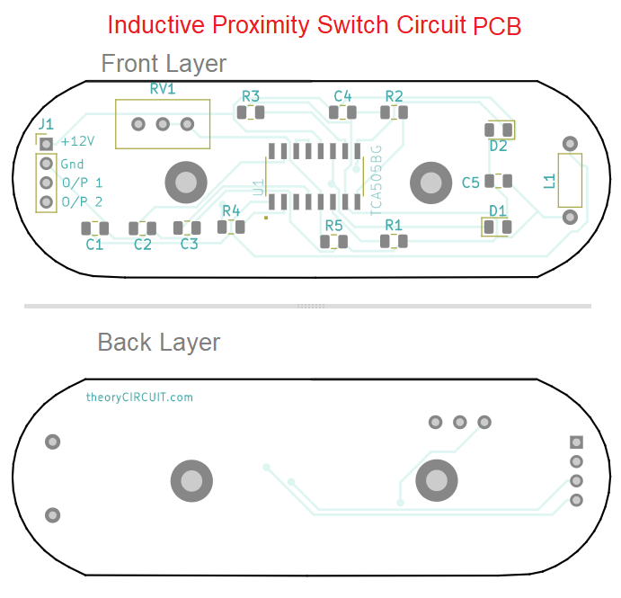
Interactive Board Viewer


circuit must be explained with arrow signs.It is easy to understsnd how current flows in circuit in which direction .