
Last Updated on April 18, 2024
In Electronic Device and Applications, Push Buttons are used in many ways to give input and controlling signal, like Power ON/OFF, Reset, and user interface etc.., A Push Button is a simple electromechanical switch that can be pressed to make or brake an electrical connection. It consists of a button and set of contacts, When you press the button then it moves and makes contacts touch together and allows current flow, when you release the button then the contacts separated and no current flow occurs. This Simple Arduino Push Button Switch Tutorial will give you detailed insight about Tactile Momentary Push Button.
There are different types of Push Button switches available, here we are going to experiment most used Momentary Push Button with tactile feedback. Which is normally open and become close when pressed, then goes back to open when released. (You may used it in Game pad, TV Remote, Reset button in development boards etc.,).
Momentary Push Button
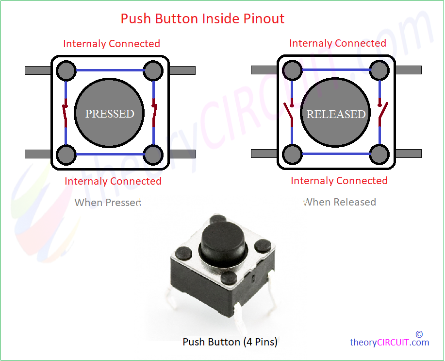
It comes in different size and length of button, mostly have four pins, two side of contacts will always in closed position and two side become close only if button pressed otherwise stays open.

Push Button Inside Pinout when the button pressed and released situations.
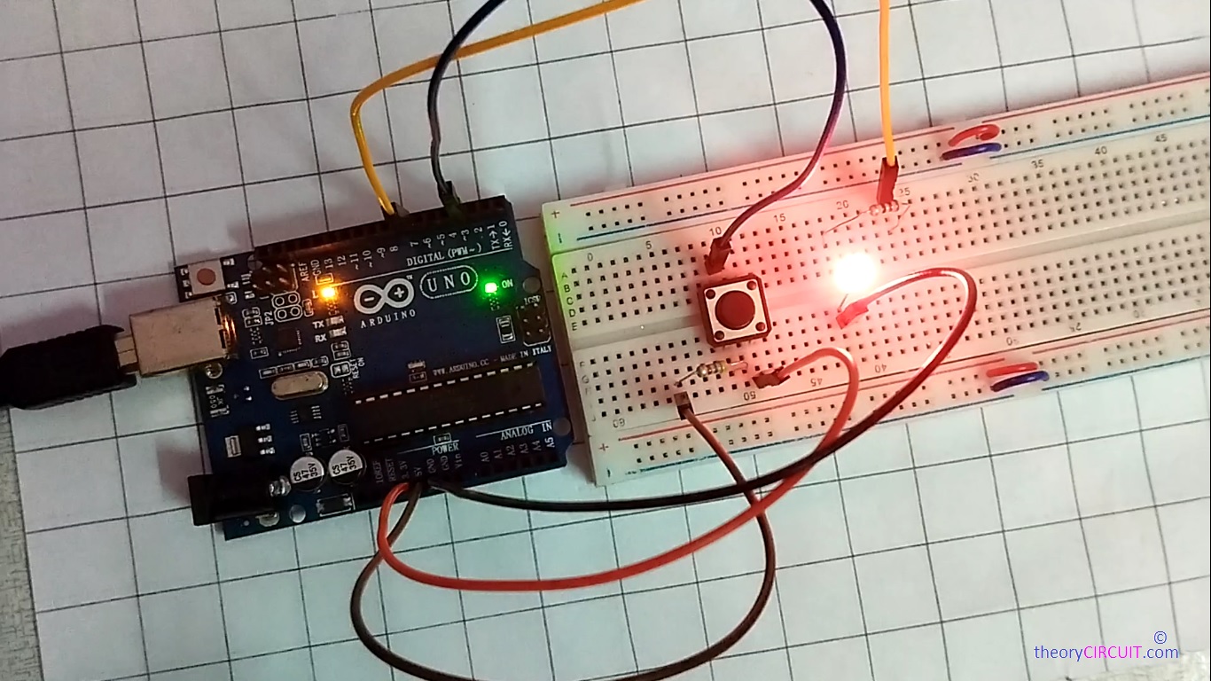
In Action!
Push Button Arduino Interface
Push Button and Arduino Interface can be done in different ways and can be used for many applications. Here is the few fundamental examples.
1. Arduino Push Button Switch State Reading
2. Push Button With Pull Up Resistor
3. Push Button With Pull Down Resistor
4. Arduino Push Button Interrupt Method
5. Arduino Push Button Debounce Method
6. Arduino Push Button LED ON / OFF with Single Click
Let’s discuss one by one with Arduino Interfacing diagram and Code.
Arduino Push Button Switch State Reading

One of the terminal of Single Push Button is connected to Arduino Digital Pin 3, In Arduino Uno Board only two External Interrupt pins are available they are Digital Pin 2 and Digital Pin 3 that is why we using Pin 3. Opposite side cross pin of push button is connected to GND of Arduino board.
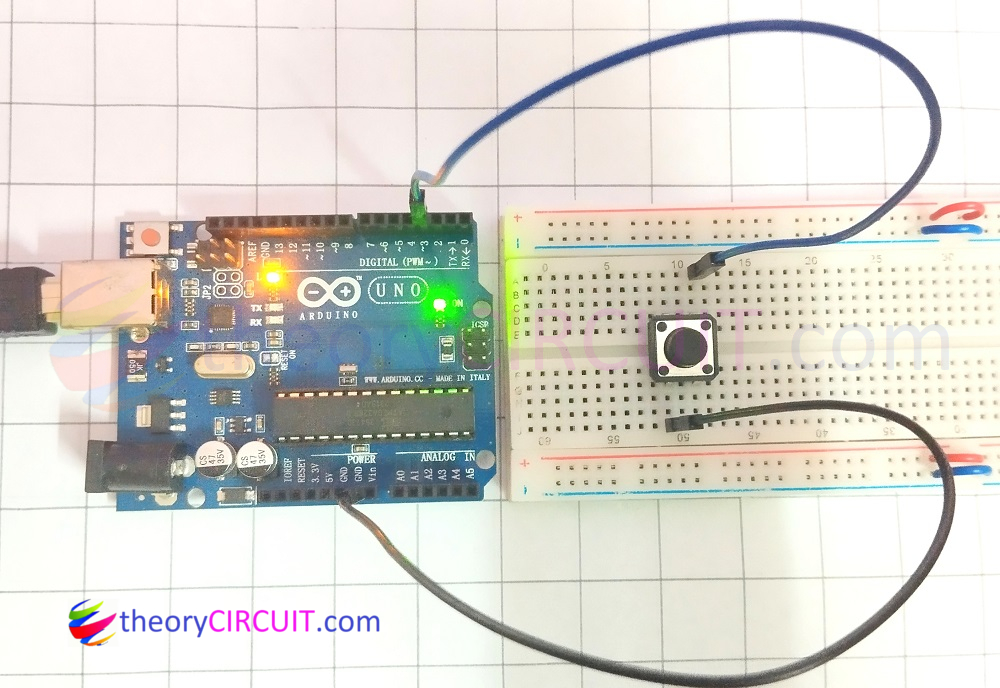
After wiring done, it is time to program the Arduino board.
Arduino Push Button Switch State Reading Code
#define ButtonPin 3

void setup() {
  Serial.begin(9600);
  pinMode(ButtonPin, INPUT_PULLUP);
}
void loop() {
  int ButtonState = digitalRead(ButtonPin);
  Serial.print("Button State: ");
  Serial.println(ButtonState);

  delay(100);
}
Serial Monitor Output Response
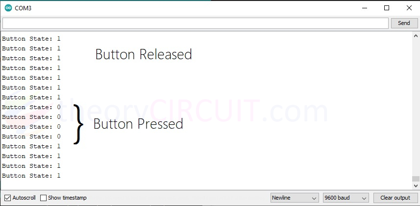
In Arduino Code First Line #define ButtonPin 3 Defines the pin for the push button, In setup Serial.begin(9600); Initialize serial communication between Arduino board and Computer at 9600 bps (bits per second). pinMode(ButtonPin, INPUT_PULLUP); line Set the push button pin as input with initial state HIGH logic. int ButtonState = digitalRead(ButtonPin); line start to Read the state of the push button in current time, Serial.print(“Button State: “); prints Button State text in serial monitor and Serial.println(ButtonState); line Print the Read state of the push button to the Serial Monitor. delay(100); line makes Delay a short time to avoid reading the button state too quickly.
Pull Up Resistor Vs Pull Down Resistor
When we connect Arduino and Push Button directly to the bias (+5, GND) that is to provide HIGH = 5V and LOW = GND input then Arduino reads that value between 0 to 5V and due to external interference and noise more than 0V can be introduced in Arduino digtal pin then it may produce wrong result. To avoid this floating condition we can Connect Resistor in Pull Up (Default HIGH input) or Resistor in Pull Down (Default LOW input) to set input condition and when you press the button opposite state will be read by Arduino.
Push Button With Pull Up Resistor

Here Pull Up Resistor is Connected to the Always closed Pin of Push Button and the GND is connected to the opposite terminal of button. Here the +5V supply is connected to the Digital Pin 3 through 4.7KΩ Resistor to make sure default HIGH input level and we have to code Arduino to read opposite When button pressed.
Arduino Push Button With Pull Up Resistor Code
#define ButtonPin 3

void setup() {
  Serial.begin(9600);
  pinMode(ButtonPin, INPUT);
}
void loop() {
  int ButtonState = digitalRead(ButtonPin);
  if (ButtonState == LOW) {
  Serial.println("Button is Pressed"); }
  else {
  Serial.println("Button is Released"); }

  delay(100);
}
Serial Monitor Response! in attached Youtube Video.
Push Button With Pull Up Resistor
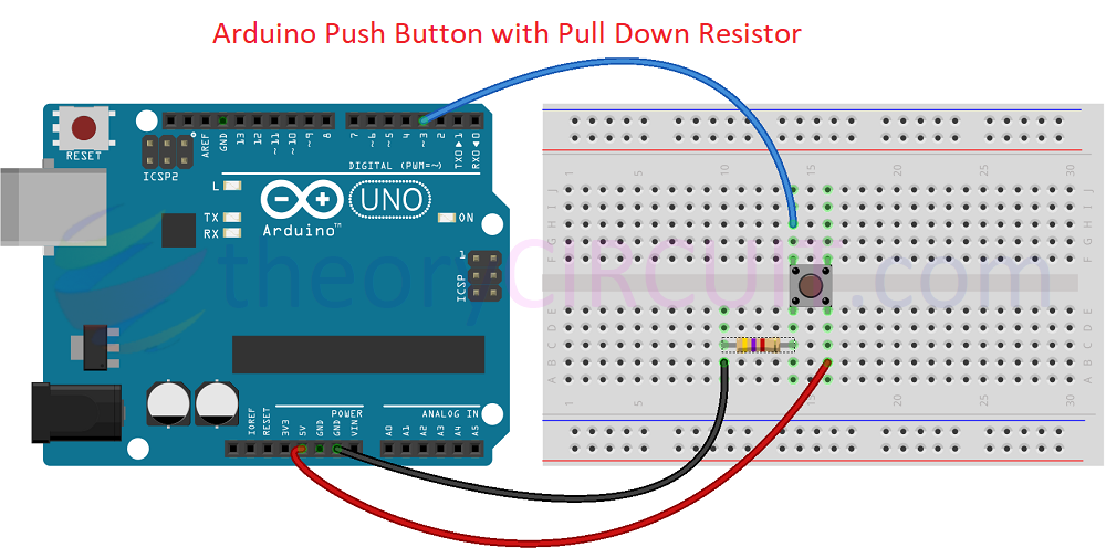
Here Pull Down Resistor is Connected to the Left side Always closed Pin of Push Button and the +5V is connected to the opposite terminal of button. Here the GND supply is connected to the Digital Pin 3 through 4.7KΩ Resistor to make sure default LOW input level and we have to code Arduino to read opposite When button pressed.
Arduino Push Button With Pull Down Resistor Code
#define ButtonPin 3

void setup() {
  Serial.begin(9600);
  pinMode(ButtonPin, INPUT);
}
void loop() {
  int ButtonState = digitalRead(ButtonPin);
  if (ButtonState == HIGH) {
  Serial.println("Button is Pressed"); }
  else {
  Serial.println("Button is Released"); }

  delay(100);
}
Video
Detecting Change of State of Push Button is useful for many applications, To read the change of state that is transition between Normal to Press state and Press to Release state (Like detecting Rising and Falling edge of Square Pulse) we can use Interrupt method. Here interrupt pin 3 is used to detect the interrupt event.
Arduino Push Button Interrupt Method

You can connect either Pull Up or Pull Down Resistor with Push Button to detect interrupt event (You have to mention it in Arduino Code). Here we used 4.7KΩ Pull down Resistor. Make connection as illustrated in the image and upload the following code.
Arduino Push Button Interrupt Method Code
#define BUTTON_PIN 3
#define LED_PIN 13 // Just for demonstration, you can change this to your desired pin for an LED

volatile bool buttonState = LOW; // Volatile variable to hold button state

void setup() {
  Serial.begin(9600);
  pinMode(BUTTON_PIN, INPUT_PULLUP); // Enable internal pull-up resistor
  attachInterrupt(digitalPinToInterrupt(BUTTON_PIN), buttonISR, CHANGE); // Attach interrupt to the button pin
  pinMode(LED_PIN, OUTPUT); // Set LED pin as output
}

void loop() {
  // Your main loop code here
  // You can still use the main loop for other tasks
}

// Interrupt Service Routine (ISR) for the button
void buttonISR() {
  buttonState = digitalRead(BUTTON_PIN); // Update button state
  if (buttonState == HIGH) {
    Serial.println("Button is Pressed");
    digitalWrite(LED_PIN, HIGH); // Turn on LED
  } else {
    Serial.println("Button is Released");
    digitalWrite(LED_PIN, LOW); // Turn off LED
  }
}
In this code on board LED of Arduino used to indicate the interrupt event and in serial monitor button state is printed. Watch the attached video for serial monito response.
Arduino Push Button Debounce Method
When you notice in the attached video, the interrupt event produce multiple prints in the serial monitor that is because of the glitch occurs in the Push Button due to mechanical parts bouncing and making short duration contact and open between internal terminals. To avoid this condition we can code in Debounce method.
Arduino Push Button Debounce Method Code
#define BUTTON_PIN 3
#define LED_PIN 13

// Debounce variables
const unsigned long debounceDelay = 50; // Debounce time in milliseconds
unsigned long lastDebounceTime = 0;     // Last time the button state changed
bool buttonState = LOW;                  // Current debounced button state
bool lastButtonState = LOW;              // Previous button state

void setup() {
  Serial.begin(9600);
  pinMode(BUTTON_PIN, INPUT_PULLUP);
  pinMode(LED_PIN, OUTPUT);
}

void loop() {
  // Read the state of the button
  int reading = digitalRead(BUTTON_PIN);

  // Check if the button state has changed
  if (reading != lastButtonState) {
    // Reset the debounce timer
    lastDebounceTime = millis();
  }

  // If the button state has been stable for the debounce delay, update the button state
  if ((millis() - lastDebounceTime) > debounceDelay) {
    // Update the button state only if it's different from the previous state
    if (reading != buttonState) {
      buttonState = reading;

      // Check if the button is pressed
      if (buttonState == HIGH) {
        Serial.println("Button is Pressed");
        digitalWrite(LED_PIN, HIGH); // Turn on LED
      } else {
        Serial.println("Button is Released");
        digitalWrite(LED_PIN, LOW); // Turn off LED
      }
    }
  }

  // Save the current button state for comparison in the next iteration
  lastButtonState = reading;
}
The above code makes Debounce time in milliseconds to read between Push Button states, so that after mechanical part settled then next state of button is read by Arduino board.
Arduino Push Button LED ON / OFF with Single Click
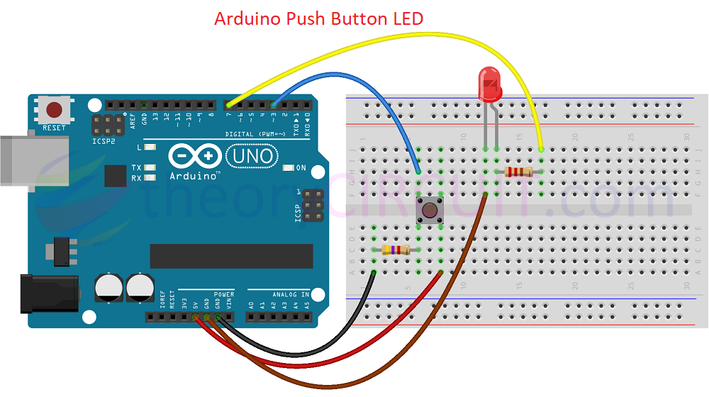
Simple LED application implemented, to achieve ON or OFF Condition of LED by single press of Push Button the following code compares previous state of output and toggles it when the button is pressed.
4.7KΩ Pull Down Resistor is connected to the Push Button and Digital Pin 3 reads state of Button, 220Ω Resistor is connected in series with LED through digital pin 7 (Output), Cathode of LED is connected to the GND Pin of Arduino. Now upload the code and check the operation.
Arduino Push Button LED Interface Code
#define BUTTON_PIN 3
#define LED_PIN 7

bool buttonState = LOW; // Variable to store the current state of the button
bool lastButtonState = LOW; // Variable to store the previous state of the button
bool ledState = LOW; // Variable to store the current state of the LED

void setup() {
  pinMode(BUTTON_PIN, INPUT); // Set the button pin as input
  pinMode(LED_PIN, OUTPUT); // Set the LED pin as output
}

void loop() {
  // Read the state of the button
  buttonState = digitalRead(BUTTON_PIN);

  // Check if the button is pressed (transition from HIGH to LOW)
  if (buttonState == LOW && lastButtonState == HIGH) {
    // Toggle the LED state
    ledState = !ledState;
    digitalWrite(LED_PIN, ledState); // Update the LED state
  }

  // Save the current button state for the next iteration
  lastButtonState = buttonState;
}
Troubleshooting
- Check the push button terminal with the help of multimeter (buzzer or Ω) readings and come to conclusion about the always closed and normally open pins.
- Choose Pull UP or Down Resistor Value between 4.7KΩ to 10KΩ.
- Make sure about the contacts of Push Button attached with Breadboard, if you are experimenting with breadboard, because the push button may have short and bend terminals.
- Still have problem let us know in the comment.