Last Updated on March 16, 2024
LED chasers are colourful when you decide to change the running speed of LEDs you have to change some components or you have to change some value.
Here this LED chaser circuit composed with Arduino uno and variable resistor as analog input by changing the value of variable resistor we can get different speed output.
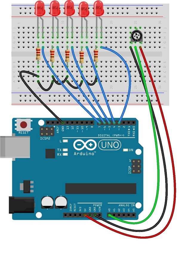
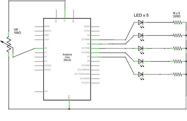
Circuit diagram
LED Chaser arduino sketch code
[code]
const int NbrLEDs = 6;
const int potPin = 0;
int val = 0;
const int ledPins[] = {2, 3, 4, 5, 6, 7};
void setup(){
for (int led = 0; led < NbrLEDs; led++)
{
pinMode(ledPins[led], OUTPUT);
}
}
void loop() {
val = analogRead(potPin);
for (int led = 0; led < NbrLEDs-1; led++)
{
digitalWrite(ledPins[led], HIGH);
delay(val);
digitalWrite(ledPins[led + 1], HIGH);
delay(val);
digitalWrite(ledPins[led], LOW);
delay(val*2);
}
for (int led = NbrLEDs; led > 0; led–) {
digitalWrite(ledPins[led], HIGH);
delay(val);
digitalWrite(ledPins[led – 1], HIGH);
delay(val);
digitalWrite(ledPins[led], LOW);
delay(val*2);
}
}
[/code]
Components List
| S.No | Name | Quantity |
| 1. | Arduino uno | 1 |
| 2. | LED | 5 |
| 3. | Resistor-220Ω | 5 |
| 4. | Connecting wires | as required |
| 5. | Trimpot(variable resistor) | 10kΩ |
 
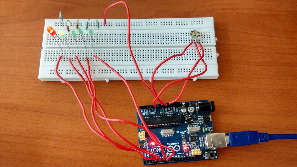
Prototype