
Last Updated on March 16, 2024
Here we added sound with visual output, yes the LED fader circuit or chaser circuit with buzzer works with pulse width modulation (pwm) output from arduino.
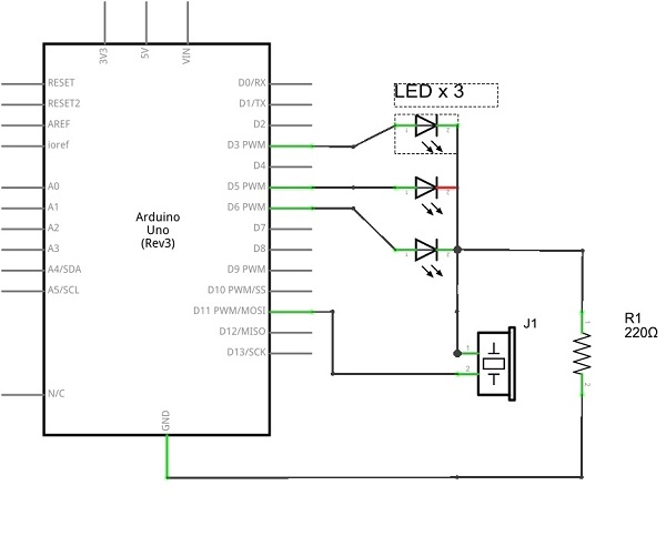
Arduino pwm outputs are taken from digital pin numbers 3,5,6 and 11 each pin connected with LED and D11 is connected with buzzer. The output intensity level can be varied through arduino sketch.
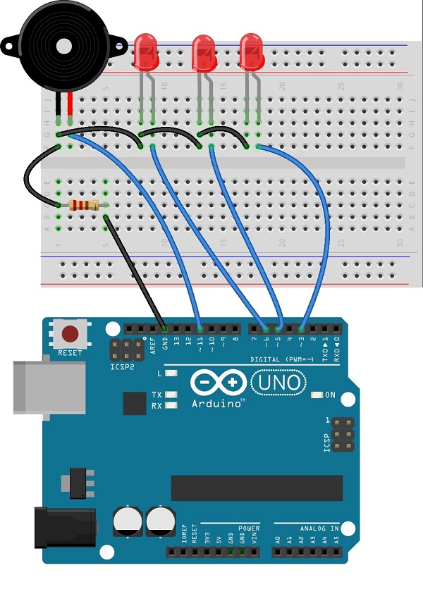
Circuit diagram
LED chaser with buzzer arduino sketch code
/*
* LedBrightness sketch
* controls the brightness of LEDs on analog output ports
* www.theorycircuit.com/led-chaser-with-buzzer
*/

const int firstLed = 3; // specify the pin for each of the LEDs
const int secondLed = 5;
const int thirdLed = 6;
const int buzzer = 11;

int brightness = 0;
int increment = 1;

void setup()
{
// pins driven by analogWrite do not need to be declared as outputs
}

void loop()
{
if(brightness > 255)
{
increment = -1; // count down after reaching 255
}

else if(brightness < 1)

{
increment = 1; // count up after dropping back down to 0
}
brightness = brightness + increment; // increment (or decrement sign is minus)
// write the brightness value to the LEDs

analogWrite(firstLed, brightness);
analogWrite(secondLed, brightness);
analogWrite(thirdLed, brightness );
analogWrite(buzzer, brightness);
delay(4); // 4ms for each step change means 2.55 secs to fade up or down

}
Components List
| S.No | Name | Quantity |
| 1. | Arduino uno | 1 |
| 2. | LED | 3 |
| 3. | Resistor-220Ω | 1 |
| 4. | Connecting wires | as required |
| 5. | Buzzer | 1 |
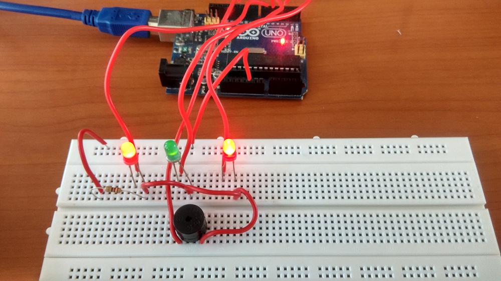
Prototype
how to change the running pattern of LED?
Change the number in – delay(4) on Arduino code.