Last Updated on March 16, 2024
This simple continuity tester circuit constructed with single npn switching transistor SL100, this circuit will give visual and audio outputs when the continuity present at the probes.
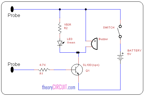
Circuit diagram
Construction & Working details
Here npn transistor switching characteristics is used to detect the closed continuity of circuit. The SL100 transistor collector terminal connected with +5V supply through buzzer and LED, the emitter terminal directly connected to battery’s negative terminal,
The base terminal act as the probe pin when the minimum bias (0.7v) is arrives at the base pin the SL100 transistor will act as a closed switch then LED and Buzzer will give output by the way we can get to know about the continuity between the two probes.
Get datasheet of SL100 here…
I tested this but it’s too sensitive. Across a 10k,100k resistor the led still lights up.
Check with different Range of Resistor Values.