Last Updated on March 16, 2024
We use different light sensor elements to detect the Light beam, for a change we can use LED device to detect light signal, Recently I found a interesting topic that is using Light Emitting Diode as a Light sensor and tried out with simple circuit. Here is the LED as a Light detector circuit.
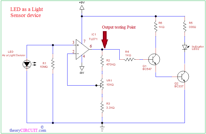
LED light sensor Circuit Diagram
Construction and Working
Normal Photodiode detects large spectrum of Light signals from 400nm to 1,000nm but LEDs are designed to emit particular wave length light by using semiconductors, so these are very narrow at sensing light signal, however a LED can do both emit and detect lights.
Color Spectrum
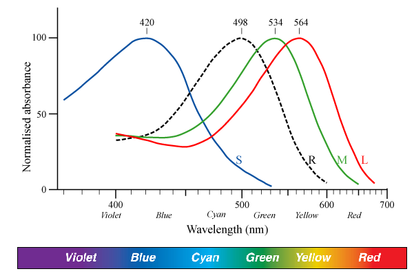
Different semiconductor materials are mixed together to design color specific LEDs like RED LEDs are made from (AlGaAs) Aluminum Gallium Arsenide. Green and Blue LEDs are made from (GaN) Gallium Nitride. Hence depends on the semiconductor light sensing characteristics may vary.
The circuit uses 5mm transparent RED LED1 as a light sensor and 5mm white LED2 as a Indicator. Here JFET input operational Amplifier TL071 is used to amplify the detected signal, dual power source (+9V to -9V) is applied to the operational amplifier, BC547 and BC337 NPN transistors drives Indicator LED, when the sensor LED in dark output of TL071 changes to high state, this turns ON Q1 and Q2 then indicator turned ON. When the light falls on LED1 then output state of TL071 becomes low and Q1, Q2 transistors turned off so there is no bias to indicator and thus LED2 turned off.
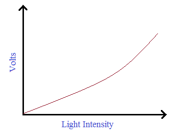
We can get varying output voltage depends on the intensity of light signal as mentioned in the circuit diagram (Check output testing point).
Output Response
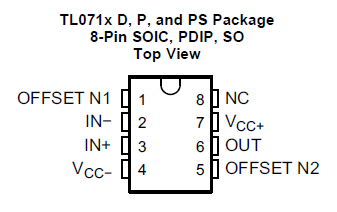
Pinout of TL071