
Last Updated on March 16, 2024
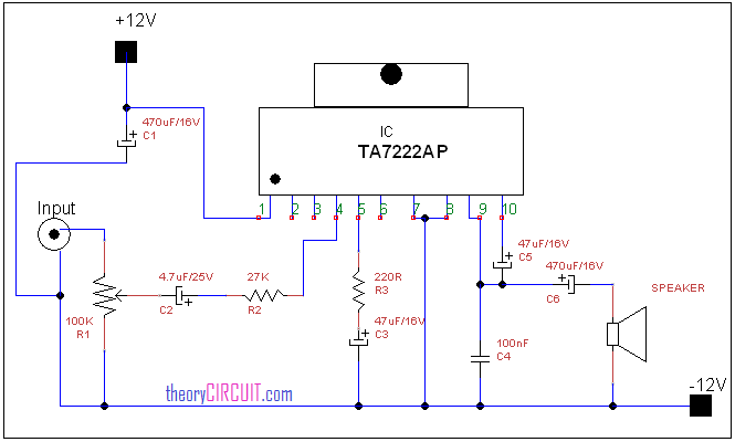
Simple 5.8W Audio power amplifier circuit designed with very few external parts, this circuit constructed based on Thoshiba TA7222AP amplifier IC.
It has adjustable closed loop gain and high sustaining over voltage with high power and low distortion output. Operating supply given to this circuit may vary between 8 to 18 volts.
Circuit Diagram
Construction & Operation details
This circuit designed to give 5.8W output power. +12V supply given to the IC bias pin1 and the pin number 2,3 & 6 are kept empty, The audio input signal given to pin number 4 through variable resitor hence we can control input amplitude, the loud speaker connected with output pin9 with 470µF capacitor and bootstrap signal through 47µF capacitor.
This amplifier circuit is suitable for 2Ω to 8Ω loudspeaker load at the output, in this circuit R1 resistor can be used as the volume controller. choose the c5 capacitor that is bootstrap signal capacitor depend on the load connected at the output.
Here you can get datasheet of IC TA7222AP
I connected a 100 uF capacitor from pin 5 to ground. But the circuit is not working that is no sound from speaker (8 ohms).
Connecting 100 uF capacitor at pin 5 won’t affect output but you need to check all the pins, terminals and supply voltage and provide adequate input signal.