
Last Updated on March 16, 2024
The LM386 is a power amplifier Integrated Circuit designed for to use in low voltage applications. LM 386 gain is internally set to 20 without most external parts and by adding few external Resistors and Capacitors we can increase gain to any value from 20 to 200. Here LM386 acoustic audio amplifier circuit designed with Gain and Bass control.
IC LM386 comes in different packages, LM386 Amplifier modules are available with different specifications but the following circuit contains additional features to control gain & bass.
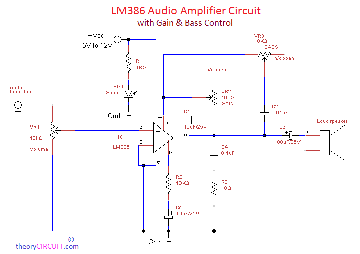
LM386 Audio Amplifier Circuit Diagram
Construction and Working
This Circuit can be easily composed with few passive components, for variable volume, gain and bass we need to put variable resistor or trimpot, Input audio is given to non inverting pin of LM386 and inverting pin is grounded. Vcc supply can be given from +5V to +12V and the output automatically biases to one half the supply voltage.
Gain control variable resistor is placed between gain pins 1 & 8 of lm386, then bass control variable resistor connected between output and pin 1 of LM386, here n/c open is no contact open terminals. The LED1 is represents power supply presence to the lm386 acoustic audio amplifier circuit.
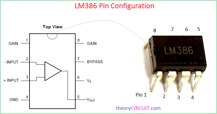
Pin Configuration
LM386 Audio Amplifier Module
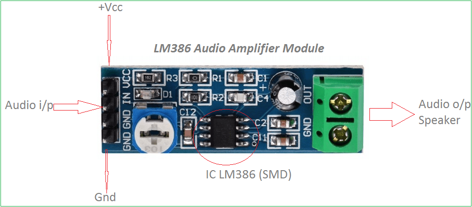
This is SMD (surface mount device) based LM386 audio amplifier module and it has only volume control trimpot.
what is the rating of loudspaker?
power and resistanc?
you can use 4 ohms or 8 ohms.