
Last Updated on March 31, 2024
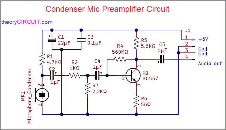
Simple easy to construct Condenser Mic Preamplifier Circuit designed by using sing transistor (BC547). This PreAmplifier circuit constructed to operate with 5V, 500mA DC supply. We know preamplifier is a electronic circuit that converts weak electric Audio Signal from sound transducer to Output Audio signal strong enough for further processing.
Here condenser microphone is a transducer which converts Acoustic sound signal into Electrical Audio Signal. This condenser mic works in the principle of two plate capacitor.
Circuit Diagram
Components Required (BOM)
| 1 | C2, C4, C5 | 1µF | CP_Radial_D4.0mm_P1.50mm | 3 | ||
| 2 | C1 | 22µF | CP_Radial_D4.0mm_P1.50mm | 1 | ||
| 3 | C3 | 0.1µF | C_Disc_D3.0mm_W1.6mm_P2.50mm | 1 | ||
| 4 | R1 | 4.7KΩ | R_Axial_DIN0204_L3.6mm_D1.6mm_P7.62mm_Horizontal | 1 | ||
| 5 | R2 | 1KΩ | R_Axial_DIN0204_L3.6mm_D1.6mm_P7.62mm_Horizontal | 1 | ||
| 6 | R3 | 2.2KΩ | R_Axial_DIN0204_L3.6mm_D1.6mm_P7.62mm_Horizontal | 1 | ||
| 7 | R4 | 560KΩ | R_Axial_DIN0204_L3.6mm_D1.6mm_P7.62mm_Horizontal | 1 | ||
| 8 | R5 | 5.6KΩ | R_Axial_DIN0204_L3.6mm_D1.6mm_P7.62mm_Horizontal | 1 | ||
| 9 | R6 | 56Ω | R_Axial_DIN0204_L3.6mm_D1.6mm_P7.62mm_Horizontal | 1 | ||
| 10 | Q1 | BC547 | TO-92_Inline | 1 | ||
| 11 | J1 | Conn_01x04_Male | PinHeader_1x04_P2.00mm_Vertical | 1 |
Condenser Mic Not mentioned in Bill of Materials.
Construction & Working
5V DC Supply directly applied to the Condenser mic through R1 Resistor. Output from Mic taken from the positive terminal Capacitor C1, C3 are used as filter capacitors, Electrical Audio signal from mic terminal is applied to the Q1 transistor Base terminal through R2, C4 elements.
Here Q1 transistor configured in common emitter configuration. Output from the transistor taken out from collector terminal followed by C5 capacitor. Audio signal from here can be Amplified by the watts range power amplifier.
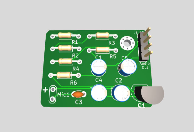
Printed Circuit Board
Condenser Mic Preamplifier Circuit Gerber Files.

Measure all components footprint before proceeding with PCB
Interactive Board Viewer


PCB
hello i work on this circuit there is lot of noisecomming continuously and when connect tis circuit out to input of PAM8403 amplifier noise is very hiogh and voice is not so much clear. How to resolve this. What is the gain of this circuit?
Hi Prince Kumar,
Continuous noise may occur due to poor filtering power supply that is power supply noise, loose connections between input source, or high gain. So try add filter capacitors like 100nF disc capacitor + 10uF electrolytic capacitor combo close to power pins. Also try to reduce input amplitude.