
Last Updated on June 28, 2024
Recently I have searched for cost effective Temperature sensor for client project with moderate sensitivity, purpose of that sensor is to detect or sense the heat and give signal that’s it, no need for precised accuracy. Then i found in internet forum that, BC547 NPN transistor can be used to detect Heat. I wondered, because i have used Thermistor, LM35, TMP36, TMP102 etc.., and never thought to use Transistor BC547 as a Heat Sensor, Then I decide to make an experiment and to find out whether it works or not.
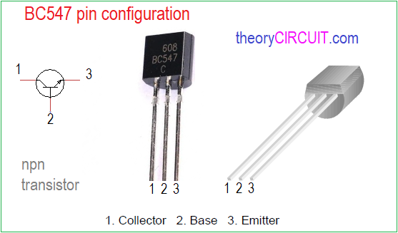
The BC547 is a widely used NPN bipolar junction transistor (BJT) and most commonly used for amplifier circuits and switching applications. It comes in TO-92 Package and also SOT23-3 package, and capable of handling 45V in Collector to Emitter pins (VCE), and handles maximum 100 mA Collector Current (IC). BC547 Transistor requires around 0.7 volts between base to emitter terminal (VBE) to turn it ON and allow significant collector current to flow. In the following circuit we going to set VBE threshold in between 0.6 and 0.65 Volts by using Variable Resistor. Then by applying external heat, we are going to make current flow (like controlled thermal runaway but without damaging Transistor).
For this Experiment you can use any one BC547 (NPN) Transistor, I heard that 2N2222 Transistor can also nicely detects heat but I didn’t tried that, may be later. 8
I have made the circuit on breadboard and used Soldering Iron as a heat source. And I got the Result!
Transistor BC547 as a Heat Sensor Circuit
Components Required
- Transistor BC547
- 5V Buzzer
- LED
- Diode 1N4007
- Variable Resistor 10KΩ
- Resistor 1KΩ, 100Ω each one
- Breadboard
- Connecting Wires
- 5V DC Power Supply
Working Video!
Construction & Working
This is a few components circuit and can be build easily, First Identify the transistor Pins exactly then place it and connect LED, Buzzer to the Collector terminal and connect the other ends to positive supply terminals through 100Ω Resistor, Make a Voltage Divider setup using 1KΩ and 10KΩ Variable Resistor. Use reverse protection diode for variable resistor and connect variable terminal to the base terminal of Transistor BC547 and connect the emitter terminal to GND (-V) pin of power supply.
Now turn ON the supply, you may see and hear beep sound or nothing. It is depends on the position of Varibale pin in the RV1 (Variable Resistor) adjust the pin to set the Threshold position. It should be between ON & OFF, that is slight change should make LED and Buzzer ON.
Now place a hot thing near or on the Transistor BC547, you will see the LED slowly starts to glow and Buzzer slowly starts to produce beep sound. When remove heat source, the LED and Buzzer slowly returns to OFF condition.8=