
Last Updated on March 16, 2024
As we know a preamplifier is an essential circuit in audio systems that deals with low-level signals, such as those produced by microphones. These initial signals are often too faint to be directly processed or amplified without the risk of introducing noise or distortion. This is where the preamp steps in. Previous condenser mic preamp circuit Design it has only one transistor and few external components and gives audio signal output suitable for low power audio amplifiers. Due to its single transistor design a signal distortion and noise occurs at output.
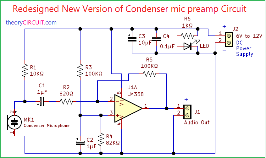
Here Redesigned New Version of Condenser mic preamp Circuit showcased with PCB Gerber files. Instead of transistor here LM358 Operational Amplifier employed as inverting amplifier mode. With low power consumption It provides versatile amplification capabilities, from small-signal amplification to larger-scale signal conditioning.
Circuit Diagram
Components Required
| 1 | C1, C2 | 1µF | CP_Radial_D4.0mm_P1.50mm | 2 | ||
| 2 | C3 | 10µF | CP_Radial_D4.0mm_P2.00mm | 1 | ||
| 3 | C4 | 0.1µF | C_Disc_D3.0mm_W1.6mm_P2.50mm | 1 | ||
| 4 | R3, R5 | 100KΩ | R_Axial_DIN0207_L6.3mm_D2.5mm_P10.16mm_Horizontal | 2 | ||
| 5 | R1 | 10KΩ | R_Axial_DIN0207_L6.3mm_D2.5mm_P10.16mm_Horizontal | 1 | ||
| 6 | R2 | 820Ω | R_Axial_DIN0207_L6.3mm_D2.5mm_P10.16mm_Horizontal | 1 | ||
| 7 | R4 | 82KΩ | R_Axial_DIN0207_L6.3mm_D2.5mm_P10.16mm_Horizontal | 1 | ||
| 8 | R6 | 1KΩ | R_Axial_DIN0207_L6.3mm_D2.5mm_P10.16mm_Horizontal | 1 | ||
| 9 | D1 | LED | LED_D3.0mm_Clear | 1 | ||
| 10 | U1 | LM358 | DIP-8_W7.62mm | 1 | ||
| 11 | MK1 | Mic | JST_VH_B2P-VH_1x02_P3.96mm_Vertical | 1 | ||
| 12 | J1 | Audio Out | TerminalBlock_bornier-2_P5.08mm | 1 | ||
| 13 | J2 | 6V to 12V | TerminalBlock_bornier-2_P5.08mm | 1 |
Construction & Working
This condenser mic pre amplifier circuit is designed to operate with 6V to 12V DC / few milliamps supply, There is a LED to indicate the presence of DC power supply and Filtered DC Supply is directly applied to Condenser Mic and Op-amp. Output signal from the mic is connected with LM358 inverting pin through C1, R2 elements. Non inverting pin is grounded through R4 and R5 Resistor provides feedback to the op-amp circuit. Pre amplified audio signal from pin 1 is connected to the audio output Connector J1.
Output gain of this circuit can be calculated as Gain(Av) = (Vout / Vin) = -(Rf / Rin) Here Rf = R5 and Rin = R2.
Op-amp configuration of this circuit involves using the negative feedback principle to achieve a controlled gain. By connecting the input signal to the inverting terminal (-) of the op-amp and feeding back a portion of the output to the same terminal through a resistor, the gain can be set according to the ratio of feedback and input resistors. You can use Variable Resistor instead of R2 to control input signal to the operational amplifier.
Printed Circuit Board
Redesigned New Version of Condenser mic preamp Circuit PCB Gerber files.

Interactive Board Viewer

