Last Updated on March 16, 2024
Identifying & Locating the broken wire Inside wall or inside plastic insulation is very difficult, Here a simple broken wire detector circuit using CD4069 (CMOS Hex inverter) and visual indicator LED, sound indicator buzzer.
By using this simple broken wire detector circuit we can identify the exact location of broken wire (note: it is most suitable for only AC supply carrying wire), this circuit detects electro magnetic field (EMF) generated by the AC carrying wire if there is a break then this circuit produce no sound and visual alert.
Circuit Diagram
Components Required
- IC CD4069
- Buzzer 5V
- LED Green, Red each one
- Transistor BC547
- Diode 1N4007
- Resistor 1MΩ,10KΩ,220KΩ,470KΩ,330Ω,1.2KΩ each one
- Variable Resistor 20KΩ
- Capacitor 100nF, 470pF each one
- Battery 9V
Construction & Working
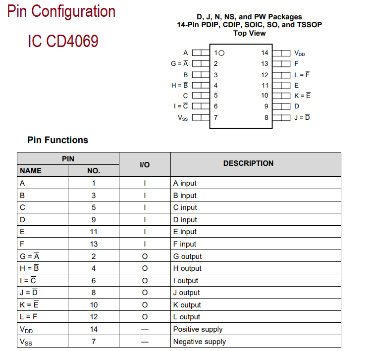
IC CD4069 is a device consist of six CMOS inverter circuits, it has 14 pins and available in different package. This IC can be used for all general purpose inverter applications. These Inverter circuits are here used to oscillate upto 1KHz frequency signal.
In this circuit Resistor R3, R4 and capacitor C2 helps IC CD4069 to oscillate signal and it is applied to buzzer element, it becomes enable while the detection of EMF on testing wire, two LEDs are connected with pin 12 of CD4069 through transistor BC547. Here this Q1 acts as a switch and makes LED1 glow during EMF detection and makes LED2 glow during absence of EMF.
This circuit should be employed with perfect length (approximately 15 cm wire with spiral) wire and it is acts as a EMF detecting antenna, sensitivity of this circuit can be varied by variable resistor VR1. This antenna wire should not directly touch high AC supply, You must be safe wile testing AC supply and do not touch supply wire with bare hands.


Hello. Can i kindly have a flow chart diagram of broken wire detection please.
It is simple Three stage Switches.