
Last Updated on March 16, 2024
Simple circuit using timer IC 555 and mosfet IRF 540 given for DC motor speed control, some DC motors have unfit RPM (rotation per minute) for projects to control speed of DC motor this simple circuit can be used.
If you are using microcontroller means you can bias this timer IC through micro controller GPIO pin and then you can control speed of motor by varying VR1 resistor.
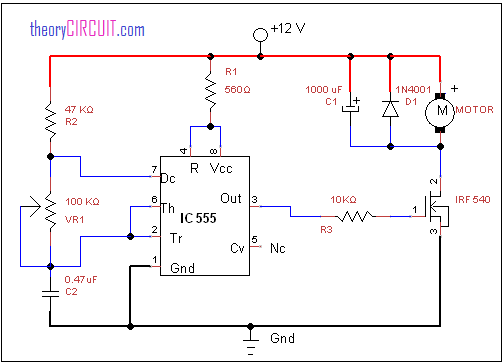
Circuit diagram
Construction and Working
The DC bias 12 volt is directly fed to the DC motor and limited by R1 resistor and then applied to timer IC 555, the control voltage pin 5 is not connected with any components, timing components VR1, C2 is connected between pin 7 and threshold, trigger pins, output is taken from pin 3 and connected with gate terminal of mosfet. The diode D1 protects motor from back emf.
When we give supply to this circuit, the timer IC produce timing pulse at pin 3 depends on VR1 and c2 elements, this timing pulse controls the mosfet hence the motor connected through mosfet is controlled, the pulse output from IC 555 has the control of DC motor speed, by varying the pulse duration we can control speed of DC motor.
Datasheet
You can get datasheet of IC LM555 here.
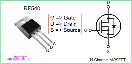
You can get datasheet of IRF 540 here.
IRF 540 pinout
Please give the bread board connection for this ckt diagram
What is the motor volt
The motor voltage is shown in the schematic as twelve (12) volts.
I need lm35 temperature circuits diagram
I need lm35 temperature circuits diagram
I need brushless motor control circuits