
Last Updated on April 14, 2024
If the constructed circuit is not giving proper output means we can check every components in the circuit and can change faulty one, but if the problem in IC means we cannot easily identify that problem. (Just kidding).
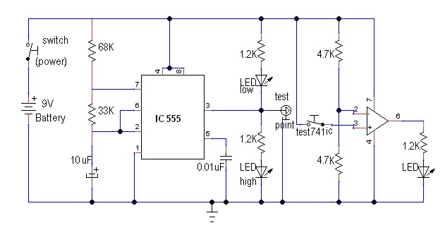
In the following circuit we can test two most common ICs that is Timer IC555 and operational amplifier IC741, use 8 pin IC base for both timer and op-amp IC.
To check IC555 place the testing IC in base and watch the output LEDs. If the two output LEDs connected with pin number 3 glows alternately means the tested IC is good otherwise this can be a fault IC. By the same way if you testing IC741 means the output LED connected with IC741 should glow otherwise it can be a fault IC.
IC 555/IC 741 tester Circuit
Components List
| S.No | Name | Quantity |
| 1. | 8 pin IC base | 2 |
| 2. | IC 555 and IC741 | 1 each |
| 3. | LED Green LED Red | 2 1 |
| 4. | Resistor 68KΩ Resistor 33kΩ Resistor 1.2kΩ Resistor 4.7kΩ | 1 1 2 2 |
| 5. | Capacitor 10uF/16V Capacitor 0.01uF | 1 1 |
| 6. | switch | 1 |
Circuit Construction and Working details
Here IC 555 testing and IC 741 testing can be done at the same time. If you want to build it separately that’s up to you. 8 Pin DIP Base is used for both ICs so that we can test and remove target IC easily. First section Timer IC 555 (Base) is configured in Astable Multivibrator mode, and it is best way to check all the terminals in IC 555 and the output is connected to two LEDs with Forward and Reverse bias connections. When the timer gives proper duty cycle pulse output, either LED low or LED high glows alternatively. Want to know how the Astable Multivibrator Works? Read here..,
Second stage of this circuit is Operational Amplifier IC741 tester. Here the IC 741 (base) is connected in comparator configuration, Inverting input pin (-) receives input through Junctions of voltage divider network formed by two 4.7KΩ Resistors and so it receives dropped voltage and Non Inverting pin (+) directly receives bias through switch, due to the difference in voltage between Inv and NInv pins operational amplifier allows difference Voltage level at the output pin, which is more than enough to drive LED. If the 741 works good then this LED should glow during the switch connected to Non Inverting pin closed.
What is the description of the circuit
Anyone can answer me