
Last Updated on March 16, 2024
To Construct short duration timers and alarm we don’t need expensive microcontrollers, we can create snooze or short duration alarm by using timer IC 555.
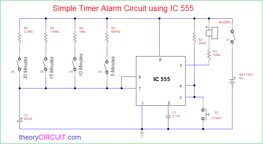
Here this circuit is constructed to give alarm buzzer sound for four different timing intervals that is 5,10,15 and 30 minutes, so we can change the timing of this circuit easily as we want.
Circuit Diagram
Construction & Working
Main part of this circuit is timer IC 555 and others are few easily available components, to give power supply to the alarm circuit 9V battery can be used other wise you can create own DC power supply 9V using step down transformer and Bridge Rectifier. Buzzer element is connected at the output pin of IC 555 and start button is connected to the pin 2 & 4 together towards DC bias through R2 Resistor.
For timer Resistor of this circuit different range of Resistor are implemented to give various timing range and only one timing capacitor (C2) is used in this circuit. Turn ON this circuit by closing S1 Switch and choose the timer range by closing s3, s4, s5 or s6 switch then push the start switch s2 and wait, the buzzer gives alarm sound depends on the timing range.
Note:- You can use one Variable Resistor instead of R3,R4,R5,R6 but you need to previously check the timing Range.
it is not working ,please tell me the solution.
what is the name of 555 ic ?
NE555 is a common chip.
Please can some one tell me how to use ic555 to time a buzzer in a water level indicator..
You can just replace the first or the last LED with a buzzer, depending whether you want to know when the container is full or empty
I am unable to find the IC555, buzzer, start pin and timing capacitor on multisims software, can i have some assistance to locate these components