Last Updated on March 16, 2024
Confused to choose Step Down Transformer for your electronic project, here is the complete Step Down Transformer Guide to help you. As we know Transformer is a device that transfers electrical energy between circuits without changing the frequency of the alternating current. All Transformers are work on the principle of electromagnetic induction, Where a changing electric current flow through a conductor produces changing magnetic field, where a changing magnetic field induces a voltage in a conductor.
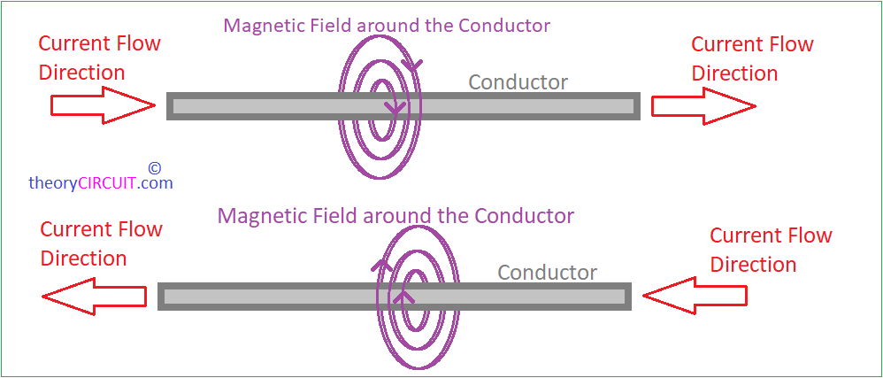
To Under stand the operation of Transformer, we should know what is happening when the Current flows through a conductor?
Consider a conductor and the Current flows through it in one direction then electromagnetic field will be produced around the conductor. It is like Faraday’s Law, Transformers are mostly static device. Now we can understand that Current flow through conductor produces Electromagnetic field, and Electromagnetic field through a conductor will induce current flow through the conductor.
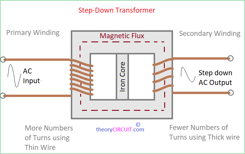
A stepdown transformer reduces the voltage of Alternating Current (AC) from the primary winding to the secondary winding. This transformation is achieved through the use of two coils of wire, known as the primary and secondary windings, which are wound around a common core typically made of laminated iron or other magnetic materials.
Step down Transformer and its Operation
A Basic Transformer either Step up or Step down or ideal will have the following three parts 1. Magnetic Core, 2. Primary Winding 3. Secondary winding. Depends on the Primary and Secondary winding Coil SWG (Standard Wire Gauge), and number of turns, the transformer acts as step up or step down. This operation can be written as,
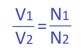
Where, V = Voltage, N = Number of Turns in the coil, 1 = Primary, 2 = Secondary
To construct Step Down transformer the ratio should be N1>N2. For a step-down transformer, N1 (Number of turns in the primary coil) is greater than N2 (Number of turns in the secondary coil), resulting in a reduced output voltage compared to the input voltage.
Step down transformers are works based on the electromagnetic induction principles. When we apply AC Supply in to the primary winding then it generates a Varying magnetic field around the coil and iron core. This varying magnetic field induces a Alternate current and Voltage in the secondary winding that is proportional to the number of turns in each winding, as previously said according to the Faraday’s law of electromagnetic induction, the ratio of turns in the primary winding to the secondary winding determines the voltage transformation.
Types of Step Down Transformer
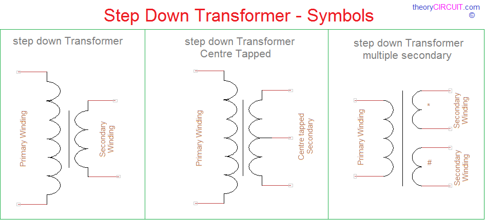
Single Phase (Example: 0-9V AC Step down Transformer)
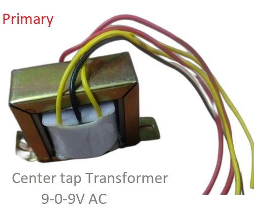
Center tap Phase (Example: 9-0-9V AC Step down Transformer)
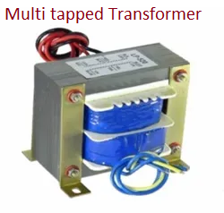
Multi tapped (Example: 0-9V, 0-5V AC Step down Transformer)
Depends on our need we can choose any transformer with different output Voltage and Current ratings.
How to Identify Primary and Secondary Coil?
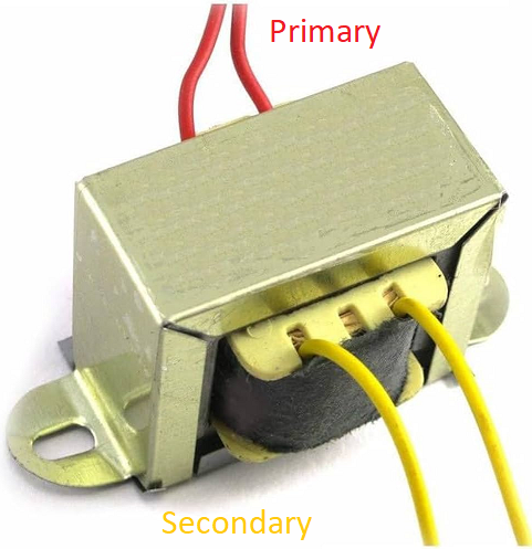
How to Identify Primary and Secondary Coil? in a step down transformer is the most asked question when there is no sticker or marking on the Core. Select Ohms measurement in Digital Multimeter and measure two coil resistance level. For step down transformer Primary coil Resistance will be Greater than Secondary coil winding. Primary Coil Ω > Secondary coil Ω.
Thing to Consider
To buy the step down transformer for your project consider the following points.
- Need of Output AC Voltage (Choose Slight higher value than need and use bridge rectifier and Regulator)
- Current Requirement (Same Voltage Transformers available with different Current ratings, Example: 9V/500 mA, 9V/ 750 mA, 9V/ 1 A, 9V/ 2 A etc..,) So choose by your need.
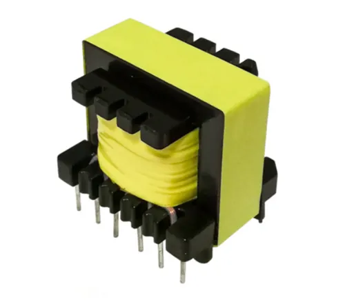
- Core Type ( Iron core for high Ampere Ratings, Ferrite Core for Better Efficiency)
- Coil Type (Copper is better than Aluminum)
