
Last Updated on March 29, 2024
When we use Microprocessor or low power controllers in circuit we need to provide additional power source to drive external peripherals. When we implement more power source then the circuit design becomes bulky and more complex. In this article 3.7V to 5V boost converter circuit is designed with DC/DC Step up Converter ME2108 Series.
IC ME2108 is a step up DC/DC converter with low supply current, this IC reduces high frequency switching noise and output can be programmed between 2.0V to 7.0V . It requires only three external components to become step up converter. This IC can be used for battery powered equipments with low supply current.
ME2108xx pin diagram
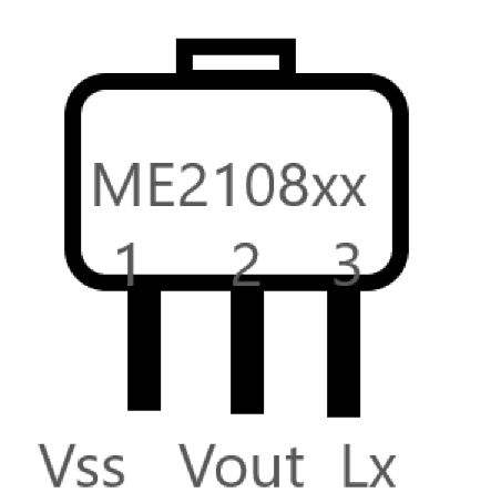
Here we taken SOT-89-3 package of ME2108 and used in dual side Printed circuit board. We Vss pin dedicated for Ground supply and Vout stands for Voltage output and Lx pin for Switch, at pin 3 we apply input supply.
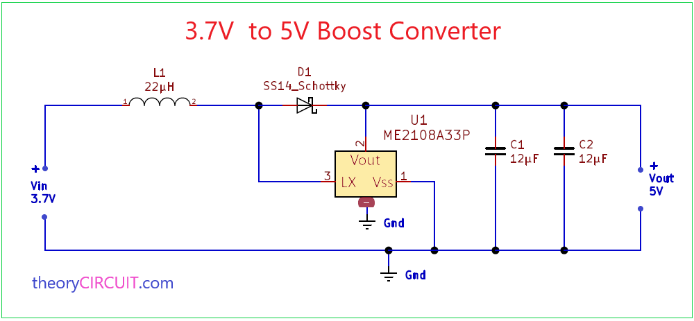
Circuit Diagram
Components Required
- IC ME2108A33P
- 22µH Inductor (220)
- Schottky diode SS14
- Capacitor 12µF (1210) =2
Circuit Assembly & Operation
As we know DC Power supply can be boosted by high frequency switching pulse by the way this prototype schematic uses the same principle to bring high voltage output from low voltage input.
Due to internal Architecture the IC ME2108 uses minimum external components. It requires Inductor at the input and Schottky diode then Capacitors at output. This IC uses 180KHz maximum switching frequency by the value of Inductor and output capacitor we can change the output voltage range. This IC can deliver 400mA output current if the input voltage 3.0V and output voltage fixed at 5.0V.
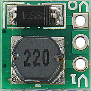
3.7V to 5V Boost Converter Breakout board
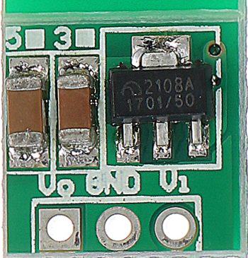
When you design the PCB for boost converter using ME2108 set external components as close as possible to the IC and minimize the connection between components and IC.
Use Capacitor with a capacity of 10µF or more in 1210 package. (you can try some other package also). Use SMD Inductor 220 for better noise less output. Use SMD Schottky diode SS14 it will provide fast switching response.
What will be the output if I add 82uH instead of 22uH?
it is limited to give output voltage depends on switching pulse.
I have made the same circuit but it’s not working I have kept the components as close as possible from the ic
Since this circuit made by SMD components you have to check the short circuit between terminals and Inductor placement. If everything perfect then use load Resistor at the output terminal and measure output voltage.
Is there any alternative to the ME2108?
Yes there is. See here,
texas instruments DC to DC boost Converters
What happens if I connect 2 x 10F supercapacitors in series instead of making 2 x 12uF parallel? Is 5F too high a value? Does it matter?
I hope it works weller